
 WhatsApp: +86 16626708626
 Email:
  Phone: +86 16626708626
Description
Key Technical Specifications
| Parameter | Value |
|---|---|
| Manufacturer | Terasaki |
| Model | ESM-103B |
| Product Type | Starter Module / PCB Card |
| Module Type | Electronic control module |
| Documented Part No. | K/87Z/4-001B |
| Other Documented Part No. | K/87Z/4-001C |
| Listed Weight | Approximately 130 g |
| Application | Marine / industrial control equipment |
| Country of Origin | Japan |
| Mounting | Equipment-specific PCB/module installation |
| Firmware | Not documented in reliable sources reviewed |
| Electrical Ratings | Not established from the available documentation |
Current aftermarket listings identify the Terasaki ESM-103B as a starter module/PCB card. Both K/87Z/4-001B and K/87Z/4-001C appear in listings associated with this model.
Important: Do not treat K/87Z/4-001B and K/87Z/4-001C as automatically interchangeable. The available sources establish that both are associated with ESM-103B, but they do not provide an OEM interchangeability statement.
Product Introduction
The Terasaki ESM-103B is a starter module PCB used in Terasaki control equipment, with aftermarket documentation specifically identifying it as a starter module. Listings associate the module with part numbers such as K/87Z/4-001B and K/87Z/4-001C.
For replacement work, the PCB suffix and physical revision matter. Before ordering, compare the complete board marking, connector arrangement, mounting configuration, and part number against the installed ESM-103B. Available sources do not provide enough OEM documentation to establish universal electrical compatibility between variants.
Installation & Configuration Guide
Stage 1: Pre-Installation Preparation — Approximately 10 Minutes
⚠️ Safety First: Place the associated equipment in a safe operating state and follow the site’s lockout/tagout procedure before removing the module. Do not assume the ESM-103B is hot-swappable.
Tools Required:
- ESD wrist strap
- Appropriate screwdriver
- Digital multimeter
- Connector/wire labels
- Smartphone or camera
- Existing equipment wiring diagram or service manual
Before removal:
- Record the complete module label.
- Photograph the installed from several angles.
- Record the complete part number, including K/87Z/4-001B or K/87Z/4-001C, if marked.
- Photograph connector positions and cable routing.
- Record any switch, jumper, or configuration settings.
- Keep the original module until commissioning is complete.
Stage 2: Removing the Old Module — Approximately 5 Minutes
- Confirm equipment isolation.
- Remove the applicable cabinet or equipment cover.
- Photograph all connectors before disconnecting them.
- Label connectors if their positions are not mechanically keyed.
- Disconnect the module carefully.
- Release the PCB/module retaining hardware.
- Remove the board without bending the PCB or stressing the connector pins.
- Inspect the mating connector and backplane for contamination, corrosion, or damaged contacts.
⚠️ Do not discard the original board. With legacy Terasaki equipment, the old PCB is often the most useful reference for confirming the exact replacement variant.
Stage 3: Installing the New Module — Approximately 5–10 Minutes
- Put on an ESD wrist strap.
- Verify the complete model and part number before installation.
- Compare the replacement PCB with the original board.
- Confirm connector locations and mechanical dimensions.
- Reproduce any documented jumper or switch settings.
- Insert the PCB carefully into its intended position.
- Ensure all connectors are fully seated.
- Secure the retaining hardware.
- Restore cable routing to its original configuration.
Self-Checklist:
- confirmed
- Full PCB part number checked
- Board revision checked
- Connector arrangement matches
- Jumper/switch settings checked
- PCB fully seated
- Retaining hardware secured
- Wiring restored
Stage 4: Power-On & Testing — Approximately 10–15 Minutes
- Perform a final visual inspection.
- Verify that no loose hardware remains inside the equipment.
- Restore power according to the equipment maintenance procedure.
- Observe the module and associated system indicators.
- Check the controller/system for startup or module-related faults.
- Verify that the associated control sequence initializes normally.
- Perform a controlled functional test.
- Confirm that no new alarm or fault condition appears.
⚠️ Do not assign a specific LED color or diagnostic code without the applicable Terasaki manual. The sources reviewed identify the as a starter module but do not provide a reliable LED diagnostic table.
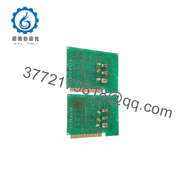
ESM-103B
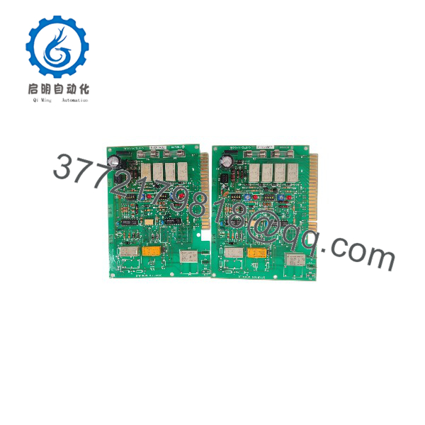
ESM-103B
Frequently Asked Questions (FAQ)
Q: What is the Terasaki ?
The is identified in current aftermarket records as a Terasaki starter module / PCB card used in industrial and marine control equipment.
Q: What part numbers are associated with ?
Listings identify K/87Z/4-001B and K/87Z/4-001C as -associated part numbers. Because the sources do not establish their interchangeability, match the complete marking on the existing board before ordering.
Q: Is a PLC CPU?
The available product records describe it as a starter module / PCB card, not as a conventional standalone PLC CPU. Some third-party listings use broader terms such as “control board,” so the exact host equipment should be verified from the installed system documentation.
Q: Can I replace K/87Z/4-001B with K/87Z/4-001C?
Do not assume direct interchangeability. Both part numbers have been listed with , but the sources reviewed do not provide an OEM cross-reference confirming that the B and C variants are electrically and mechanically identical.
Q: Can the be hot-swapped?
There is insufficient documentation to establish hot-swap capability. Unless the specific Terasaki equipment manual explicitly permits energized replacement, isolate power before removing the module.
Q: Is still available?
It remains available through aftermarket industrial and marine-equipment suppliers. Current listings include used units and stock listings, although actual condition and availability vary.
Q: What should I verify before purchasing a replacement?
Verify , the complete K/87Z/4-001B or K/87Z/4-001C marking, connector configuration, PCB layout, mounting arrangement, and physical condition. For a legacy control system, matching the complete board marking is safer than ordering solely from the model name.



