
 WhatsApp: +86 16626708626
 Email:
  Phone: +86 16626708626
Description
3. Key Technical Specifications
| Parameter | Specification / Value |
| Manufacturer | TMEIC (Toshiba Mitsubishi-Electric) |
| Part Number | ARND-3110 |
| Module Type | Microprocessor & Drive Control Card |
| Nominal Supply Voltage | 24 V DC (±10%) |
| Internal Power Dissipation | 15 W maximum |
| Communication Ports | Dual High-Speed Optical Fiber Links |
| Feedback Interfaces | Incremental Quadrature Encoder / Resolver Pass-Through |
| Digital Inputs / Outputs | 8 Dedicated 24 V DC Inputs / 4 Relay Outputs |
| Operating Temperature | 0 to 55 °C (32 to 131 °F) |
| Storage Temperature | −20 to 70 °C (−4 to 158 °F) |
| Humidity Range | 5 to 95% non-condensing |
| Mounting Orientation | Card cage / Rack slot mounted |
4. Product Introduction & Supply Chain Strategy
The TMEIC ARND-3110 is a primary drive control board engineered for high-demand variable frequency drives and automation systems across steel processing, paper mills, and heavy manufacturing lines. It performs real-time execution of motor control algorithms, high-speed fiber-optic pulse width modulation (PWM) signal distribution, and encoder feedback calculations.
This product is supplied exclusively as Brand New Surplus inventory. Sourcing this module in New Surplus condition provides direct Total Cost of Ownership (TCO) optimization by securing factory-level operational life without paying OEM list premiums or enduring long lead times. Because this series faces rising obsolescence, holding an unused, factory-sealed spare on-site eliminates the severe risk of multi-day downtime caused by sudden drive failures or degraded internal component aging common in third-party repairs.
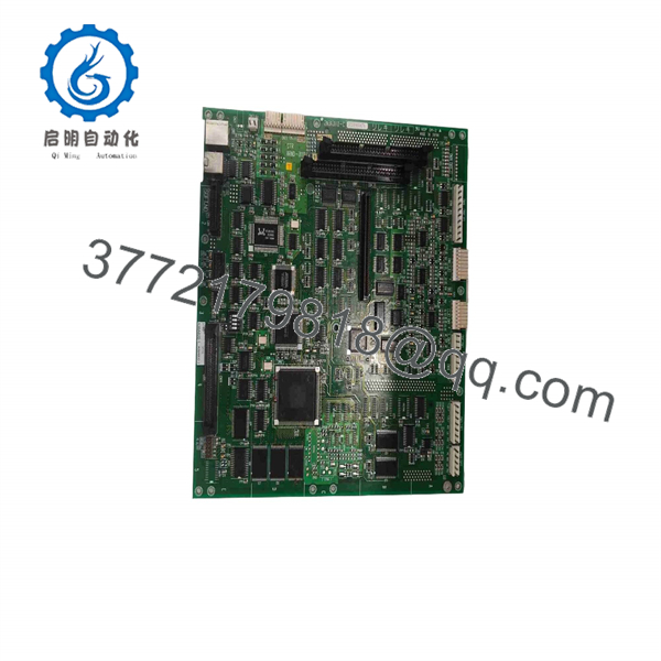
ARND-3110
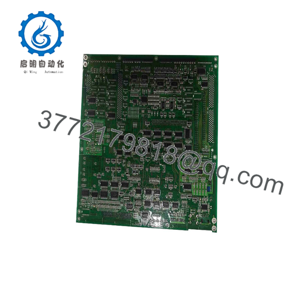
ARND-3110
5. Installation & Configuration Guide
1.Stage 1: Pre-Installation (Prep & Safety):Prerequisite & Safety Lockout.
Perform lock-out/tag-out (LOTO) on the main drive power feed and wait at least 10 minutes for internal DC bus capacitors to discharge down to 0 V before opening the drive enclosure. Put on a grounded ESD wrist strap connected to the cabinet frame. Photograph all existing wiring connections, fiber-optic cable positions, and on-board DIP switch / jumper settings on the failed ARND-3110 module for reference.
Verification: Verify zero voltage on the main DC bus terminals using a calibrated multimeter.
2.Stage 2: Removal:Component Extraction.
Disconnect terminal blocks, encoder connectors, and fiber-optic cables by pulling directly on the connector bodies—never pull on the fragile optical fibers themselves. Loosen the top and bottom retaining screws on the front panel. Carefully slide the module straight out along its guide rails to avoid bending backplane pins or scratching neighboring cards.
Verification: Inspect the rack guide rails and backplane socket for debris, bent pins, or signs of overheating.
3.Stage 3: Installation (Clone & Seat):Hardware Setup & Insertion.
Set the DIP switches and jumpers on the new ARND-3110 module to mirror your original photo precisely (e.g., node address, communication baud rate, encoder signal selection). Align the board with the rack card guides and push firmly until the backplane connector fully seats. Tighten the front retaining screws to hand tightness. Reconnect all fiber-optic cables and wiring plugs into their respective ports.
Verification: Gently pull on connected terminal blocks and optical connectors to confirm physical latching.
4.Stage 4: Power-On & Testing:System Diagnostics.
Apply 24 V DC control power to the rack (keep main high-voltage 3-phase power disconnected). Observe the LED indicators on the front panel of the ARND-3110. Ensure the “PWR” or “READY” LED lights up solid green without a latching “FAULT” or “ERR” light. Download or verify drive parameter sets via your programming software if prompted.
Verification: Confirm the drive control unit establishes a clean communication handshake over the fiber link and reports zero active fault codes.
6. Firmware/Software Versions & Upgrade Notes
- Recommended Firmware: Firmware Revision V3.12 (or matching the drive system’s baseline firmware parameter file).
- Compatibility Matrix: Firmware versions below V2.8 do not support modern fiber-optic interface modules and may cause loss-of-communication (F004) trip faults on system startup.
- Firmware Swap Warnings: Never attempt an unguided firmware flash or upgrade while swapping out a failed board during an active outage. A firmware jump from legacy V1.x/V2.x up to V3.x can alter parameter mapping tables, corrupt stored EEPROM tables, or misconfigure motor feedback scaling. Always match the replacement board’s firmware build to the original module or re-upload your proven site backup config file directly after hardware installation.
7. Frequently Asked Questions (FAQ)
Q: Is this TMEIC ARND-3110 card brand new, or has it been pulled and cleaned up?
A: This module is a genuine Brand New Surplus unit. It has never been installed in an active control panel, never pulled from a decommissioned plant, and never subjected to component-level circuit repairs. It retains full factory integrity, pristine backplane contacts, and clean solder joins.
Q: Why does New Surplus cost more than refurbished boards on the market?
A: Refurbished boards are used parts that have already suffered thousands of thermal cycles. Electrolytic capacitors and optical transceivers age over time, creating hidden failure risks that cause sudden trips months down the road. Spending 20-30% more for New Surplus guarantees a fresh, 10-15 year operational lifespan and protects your facility against sudden $50,000/hr downtime events.
Q: Is the module hot-swappable during drive operation?
A: No. Removing or inserting the while control power is applied can arc backplane pins, corrupt flash memory, or cause immediate short circuits on the 24 V rail. Always isolate control and main line power before pulling or seating the module.
Q: Do I need to program this board before the drive will run?
A: The holds system parameters and drive control logic. If your drive system stores parameters on a master processor memory card or upper PLC controller, the parameters may auto-load upon boot. However, if parameter storage is local to the board, you must clone the DIP switch hardware settings and download the drive parameter backup file via TMEIC configuration software.
Q: What warranty coverage comes with this New Surplus board?
A: We provide a full 1-year functional warranty from the date of shipment. Every undergoes systematic inspection, ESD-safe handling, and visual/electrical validation prior to dispatch.



