
 WhatsApp: +86 16626708626
 Email:
  Phone: +86 16626708626
Description
Key Technical Specifications
| Parameter | Specification |
|---|---|
| Manufacturer | TMEIC / Toshiba |
| Model | ARND-3110 |
| Associated P/N | 2N3A3110-C |
| Board Designation | CTR |
| Main Function | Main control circuit |
| Drive System | T300MVi medium-voltage drive |
| Control Architecture | Drive main controller |
| Measurement Analog Outputs | 5 channels, D/A1–D/A5 |
| Analog Output Function | Programmable measurement outputs |
| Example Output Range | 0–10 V in documented configurations |
| Processor / CPU | Not verified from accessible OEM documentation |
| Input/Output Count | Not applicable as a conventional PLC I/O module |
| Communication Interfaces | Configuration-dependent; exact board interfaces should be verified from drive drawings |
| Condition | Legacy / discontinued |
The TMEIC documentation specifically shows five measurement analog outputs, D/A1 through D/A5, on the CTR board. Output data, gain, and offset can be configured through the maintenance PC interface.
For example, the documentation shows speed feedback being assigned to D/A1 and scaled to 0–10 V, while torque reference can be assigned to another analog output. These outputs are therefore part of the drive’s measurement/control architecture rather than ordinary PLC analog I/O.
Product Introduction
The TMEIC ARND-3110 is the CTR main control board used in TMEIC/Toshiba medium-voltage drive systems. TMEIC’s T300MVi documentation places ARND-3110 at the center of the control-board architecture, alongside dedicated gate-signal, optical-link, voltage-detection, external-I/O, and operator-interface boards.
The board also provides five configurable measurement analog outputs. Their source data, gain, and offset can be set through the maintenance tool, allowing internal drive variables such as speed feedback and torque reference to be made available as analog signals.
Installation & Configuration Guide
Stage 1 — Pre-Installation Preparation
- Confirm the exact board marking, including ARND-3110, revision, and any additional suffix.
- Verify the drive model and rating against the electrical drawings.
- Obtain the existing drive parameter/configuration backup.
- Record connector positions, board settings, and diagnostic information.
- Prepare ESD protection and appropriate insulated tools.
⚠️ Do not treat ARND-3110 as a universal replacement board. TMEIC documentation states that certain board information is job/inverter specific and should be checked against the specific inverter drawings.
Stage 2 — Removing the Existing Board
- Stop the drive using the approved shutdown sequence.
- Isolate the medium-voltage main circuit and control power according to the site’s electrical safety procedure.
- Verify absence of hazardous voltage before opening the cabinet.
- Label all connectors before disconnecting them.
- Remove the existing CTR board without damaging the backplane or mating connectors.
- Inspect the board connector and cabinet wiring for contamination or mechanical damage.
⚠️ TMEIC’s T300MVi manual explicitly warns that the prescribed powering-on sequence must be followed and that main/control power should not be switched off improperly while the motor is running.
Stage 3 — Installing the Replacement Module
- Compare the replacement board with the removed ARND-3110.
- Confirm the exact hardware revision and job-specific configuration.
- Carefully align the board with the appropriate mounting and connector positions.
- Secure the board mechanically.
- Reconnect all wiring according to the original drawings.
- Verify that signal connectors are not crossed with those belonging to the GSD, VDET, XIO, or other drive boards.
Stage 4 — Power-On & Testing
- Confirm that all covers, shields, and protective barriers are installed.
- Restore control power following the manufacturer’s sequence.
- Check drive controller diagnostics and board status.
- Verify communication between the controller and associated drive boards.
- Confirm measurement analog outputs D/A1–D/A5 where applicable.
- Check speed-feedback and torque-reference values against expected values.
- Perform a controlled motor test before returning the drive to production.
⚠️ Do not immediately enable full-load operation after a controller-board replacement. Verify feedback, control references, interlocks, and protection functions first.
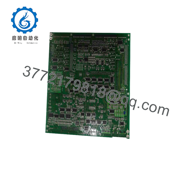
ARND-3110
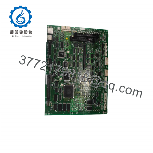
ARND-3110
FAQ
1. What is the TMEIC ?
is the CTR main control circuit board used in TMEIC/Toshiba drive systems, including the T300MVi medium-voltage drive architecture.
2. Is a PLC digital output module?
No. Some reseller pages incorrectly describe it as a digital-output module. TMEIC’s own drive documentation identifies as the main control circuit, or CTR board.
3. What is the relationship between and 2N3A3110-C?
Available industrial spare-parts records associate 2N3A3110-C with the controller board. Radwell also lists 2N3A3110C and as alternate identification for the same discontinued board.
4. How many analog outputs does provide?
The TMEIC documentation describes five measurement analog outputs, designated D/A1 through D/A5. Their output data, gain, and offset can be configured through the maintenance tool.
5. Which drive systems use ?
The board is documented in the T300MVi medium-voltage drive architecture. Other TMEIC/Toshiba drive platforms may use related revisions, so the complete drive model and board suffix should be checked before procurement.
6. Is still manufactured?
Available industrial-part records identify the board as discontinued. Replacement sourcing therefore generally involves existing inventory, surplus stock, repair, refurbishment, or exchange units.
7. What should be verified before purchasing an replacement?
Verify the complete board number, suffix/revision, drive model, drive voltage/rating, job-specific drawings, connector arrangement, and existing firmware/configuration. This is particularly important because the T300MVi documentation notes that some board selections are specific to the individual inverter/job.



