
 WhatsApp: +86 16626708626
 Email:
  Phone: +86 16626708626
Description
Key Technical Specifications
- Manufacturer: TMEIC Global
- Part Number: ARND-3110A
- Product Description: Controller Board PWB / PLC Add-On Board
- Equipment Category: Industrial automation control hardware
- Form Factor: Printed wiring board; installation-specific assembly
- Primary Application: Replacement board for installed TMEIC control systems
- Lifecycle Status: Discontinued by manufacturer
- Firmware: Site-specific; verify against removed board before installation
- Configuration: May depend on board-mounted jumpers, DIP switches, and host-system configuration
- Communication Interface: Verify from the installed system documentation and connector layout before ordering
- Supply Requirements: Determined by host rack, chassis, or control cabinet; do not apply external power directly to the board
- Replacement Rule: Match the complete ARND-3110A number, board revision, connector layout, and installed configuration
Public distributor records identify ARND-3110A as a discontinued TMEIC Global controller board PWB / PLC add-on board. Published listings do not provide sufficiently reliable electrical ratings, pinouts, memory capacity, dimensions, or protocol details for this exact suffix, so those details must be verified from the original board label and OEM documentation before purchase or installation.
Product Introduction
The TMEIC ARND-3110A is a controller printed wiring board used as a replacement component in TMEIC industrial automation and control installations. This discontinued ARND-3110A board is normally sourced for maintenance spares, outage recovery, and repair of an existing system where the installed board must be matched exactly.
Buyers choose the exact TMEIC ARND-3110A part number when retaining the original control architecture matters more than redesigning the cabinet. Confirm the board revision, connectors, firmware, jumper settings, and host rack compatibility before ordering. Distributor listings classify the unit as discontinued, making traceable surplus inventory important for planned spares.
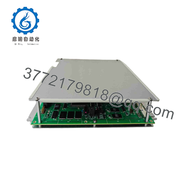
ARND-3110A
Troubleshooting Quick Reference
| Symptom | Possible Cause | Relevance to This Part | Quick Check Method | Recommendation |
|---|---|---|---|---|
| No system power or no cabinet LEDs | Failed 24 V DC supply, blown fuse, loose power terminals, tripped breaker | ❌ Low | Measure the control supply at the rack power-supply output with a Fluke 115 or equivalent; verify incoming AC/DC feed and fuse continuity | Repair the power path before condemning the |
| Host controller does not boot after startup | board fault, incorrect seating, connector damage, firmware/configuration mismatch | ✅ High | With power removed, inspect edge connectors and board guides; reseat the board; compare all labels and revisions with the removed unit | If the fault follows the after correct installation, arrange replacement or bench evaluation |
| Intermittent controller faults after warm-up | Loose connection, oxidized contacts, power-supply ripple, temperature-related component failure | ✅ Medium | Record fault timing; inspect for discoloration or capacitor leakage; check supply ripple under load with an oscilloscope if available | Verify power quality and cooling first; replace the board if the symptom tracks the module |
| Communication timeout or network watchdog alarm | Incorrect node address, baud-rate setting, firmware mismatch, damaged network cable, upstream master issue | ✅ Medium | Photograph the old board’s DIP switches and jumpers; check network termination and cable continuity; collect controller diagnostics before removal | Match the old physical settings exactly and verify firmware compatibility before replacing the board |
| I/O points do not respond | Failed field wiring, local I/O module fault, interposing relay issue, inhibited logic | ❌ Low | Check adjacent I/O card LEDs; measure field voltage at terminal blocks; force or monitor the relevant tag only under approved site procedures | Troubleshoot the field circuit and local I/O first; do not replace the as the first step |
| Fault occurs immediately after replacement | Board revision mismatch, wrong part suffix, omitted configuration transfer, incorrectly installed connector | ✅ High | Compare part number, revision label, connector keying, jumper positions, and any removable memory/configuration devices | Remove power, reinstall the original board if safe, and verify every configuration detail before energizing again |
| Random resets during high-load operation | Backplane supply overload, inadequate cooling, poor grounding, board fault | ✅ Medium | Measure rack supply under load; inspect cabinet fans and filters; verify protective-earth continuity | Keep at least a 20% power-supply margin and correct thermal or grounding defects before replacing hardware |
| Visible corrosion, rework marks, or damaged connectors | Storage damage, previous repair, contamination, mechanical damage | ✅ High | Inspect under bright light and magnification; compare connector pins and board surfaces with the removed unit | Do not install a visibly compromised board in a production system; request photos and traceability documentation |
❗ Firmware revision mismatch: Record the old board’s firmware or label information before removal. I have seen a replacement board pass power-up, then hold up commissioning for days because the installed master rejected a slightly different protocol implementation. Treat revision matching as a pre-install requirement, not an afterthought.
❗ DIP switches and jumpers: Take clear photos before touching the old unit. Seriously. Factory defaults may not match the site’s node address, baud rate, termination, or operating mode. Mirror every physical setting unless the OEM documentation calls for a deliberate change.
❗ Connector and wiring assumptions: Do not wire from memory. Similar-looking boards can use different connector assignments or grounding arrangements. Compare the OEM drawing, terminal map, and board silk-screening before re-energizing the cabinet.
❗ Power budget: A replacement assembly can expose an already marginal rack supply. Measure the backplane supply under actual load and retain at least a 20% capacity buffer.
❗ ESD handling: Use a grounded wrist strap and an ESD-safe work surface. Static damage can create intermittent faults that only appear after the board has warmed up in service.
For support, provide clear photos of both board labels, the installed rack position, connector faces, any jumper or DIP-switch settings, and the complete diagnostic log. Keep these checks in mind and you will save yourself 90% of typical rework time.
Frequently Asked Questions
Is the TMEIC still manufactured?
No. Distributor records list the TMEIC as discontinued by the manufacturer. Availability therefore depends on verified surplus inventory, refurbished stock, and the condition of the specific unit offered. For a critical asset, buy a matched operational spare rather than waiting for a failure during an outage.
Is a direct replacement for ARND-3110?
Do not assume that it is. The “A” suffix can indicate a revision, hardware change, or approved variant, but public listings do not establish universal interchangeability between ARND-3110 and . Match the full part number, board revision, connector layout, firmware information, and physical configuration against the removed unit before ordering.
Can I hot-swap the ?
Do not hot-swap it unless the exact TMEIC system manual explicitly identifies this board position as hot-swappable. A controller PWB or add-on board can carry backplane power, logic signals, and configuration dependencies. Pulling it live may damage the board, host rack, or connected equipment. Shut down under the site’s approved lockout/tagout procedure first.
Will I lose the program or settings when replacing this board?
Possibly. The answer depends on where the system stores its application program and configuration: a host controller, removable memory device, nonvolatile memory on the board, or an engineering workstation backup. Before removal, back up the controller project, record board labels and firmware, photograph all switches and jumpers, and identify whether any removable memory must transfer with the replacement.
What should I verify before purchasing an ?
Verify these items against the installed board:
- Complete manufacturer name and exact part number
- Board revision, serial-number format, and date code
- Connector count, keying, and orientation
- Host rack, cabinet, or controller family
- Firmware label or readable firmware version
- DIP-switch and jumper positions
- Any daughterboard, memory module, or calibration component
- Required condition: New Original/New Surplus or Refurbished tested
The part number alone is necessary, but on legacy control boards it may not be sufficient.
Why is new-surplus stock usually less expensive than factory supply?
New-surplus inventory normally comes from unused maintenance spares, canceled projects, plant closures, or excess inventory rather than current factory production. The lower price does not automatically mean the unit is inferior, but you should require condition photos, serial-number traceability where available, packaging details, test documentation, warranty terms, and confirmation that the seller will support an RMA if the board does not match the listing.
What testing should a refurbished receive?
A credible refurbished-unit process should include inbound visual inspection, serial-number and anti-counterfeit checks, connector inspection, controlled power-up in a compatible test rack, status/boot verification, communication testing where the interface is available, a sustained load or thermal run, and a documented test report. Electrical checks should include protective-earth continuity and insulation testing only when applicable to the board design. The seller should use ESD-safe packaging and provide test photos or video on request.
For New Original / New Surplus inventory, the priority is traceability and preservation: no corrosion, no rework marks, intact connectors, proper ESD packaging, and documented storage condition. Do not request a hipot test on a low-voltage controller board unless the OEM procedure specifically permits it; an inappropriate test can cause the failure you were trying to prevent.



