
 WhatsApp: +86 16626708626
 Email:
  Phone: +86 16626708626
Description
Key Technical Specifications
| Parameter | Value |
|---|---|
| Model | ARND-3120 |
| Manufacturer | TMEIC |
| Product Category | PLCs / Machine Control PC Board |
| Product Function | Sensorless vector control; pulse generator |
| Product Family | TMDrive-30 |
| Board Type | Control / Add-On Board |
| Alternate Part Number | 2N3A3120-D |
| Analog Input Channels | 2 general-purpose channels |
| Analog Input Resolution | 12-bit A/D conversion |
| Analog Input Range | ±10 V; 4–20 mA possible through jumper configuration |
| Digital Conversion Range | −2,047 to +2,047 for ±10 V input |
| Input Adjustment | Software gain and offset processing |
| Lifecycle | Discontinued |
| Published Board Weight | Approximately 6.0 lb / 2.72 kg |
TMEIC documentation specifically identifies ARND-3120 as the external terminal block board used for analog input and I/O functions in the relevant drive system. The documented analog section provides two general-purpose analog inputs with 12-bit conversion; ±10 V is the standard configuration, while 4–20 mA requires the appropriate jumper setting.
A separate equipment manual also identifies ARND-3120 as the XIO input/output circuit board used for emergency-operation and E-HOLD signals.
Radwell lists ARND-3120 as a TMEIC Global PC board for TMDrive-30, with the functions sensorless vector control and pulse generator, and identifies the manufacturer’s status as discontinued.
Product Introduction
The TMEIC ARND-3120 is a legacy control/PC board associated with the TMDrive-30 drive platform. Available technical documentation identifies ARND-3120 in the system’s XIO architecture, including analog input and external I/O functions. Its analog interface provides two general-purpose channels with 12-bit A/D conversion.
For maintenance teams supporting existing TMDrive-30 installations, the important issue is revision and system compatibility rather than simply matching the board number. is listed as discontinued, so verify the complete nameplate, associated drive configuration, connectors, and existing parameter settings before specifying a replacement.
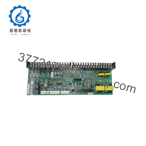
ARND-3120
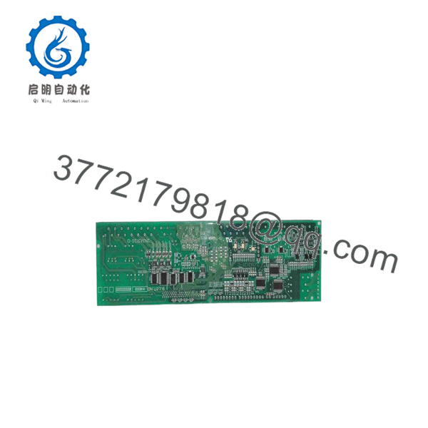
ARND-3120
Installation & Configuration Guide
Stage 1: Pre-Installation Preparation — About 5–10 Minutes
⚠️ Safety First: Stop the drive and place the machine in a safe state. Isolate the applicable power sources and apply the site’s lockout/tagout procedure. Verify that hazardous voltage has been removed before touching the board or associated wiring.
Tools Required:
- ESD wrist strap
- Insulated screwdriver set
- Multimeter
- Wire labels
- Smartphone or camera
- Existing TMDrive-30 documentation
Before removing the existing :
- Record the complete part number and board revision.
- Photograph every connector and terminal position.
- Record existing jumper positions.
- Photograph all configuration switches and wiring.
- Record drive parameters and application-specific settings.
- Identify every analog input and I/O signal connected to the board.
- Keep the old board available until commissioning is complete.
⚠️ Pay particular attention to the analog-input jumper configuration. TMEIC documentation states that the analog inputs are configured for voltage input and require jumper changes when used with 4–20 mA signals.
Stage 2: Removing the Old Module — About 5 Minutes
- Confirm the equipment is de-energized.
- Verify the absence of hazardous voltage with an appropriate meter.
- Photograph the board and connector arrangement.
- Label field wiring before disconnecting it.
- Disconnect connectors carefully without pulling on individual conductors.
- Release the board mounting hardware according to the TMDrive-30 enclosure arrangement.
- Remove the while protecting the PCB and connectors.
- Inspect connectors for oxidation, bent contacts, contamination, or mechanical damage.
⚠️ Do not discard the original board immediately. It provides the most reliable physical reference for jumper settings, connector locations, and wiring.
Stage 3: Installing the New — About 5–10 Minutes
- Verify the replacement is marked .
- Compare connector locations with the original board.
- Confirm the board revision and any associated identification markings.
- Use ESD precautions before handling the PCB.
- Install the board in the original mounting position.
- Reconnect each connector according to the photographs and wiring documentation.
- Restore the original jumper configuration.
- Pay particular attention to analog-input configuration.
- Secure the board and connectors before energizing the system.
Configuration Clone — Critical:
If the existing application uses 4–20 mA analog signals, do not assume the replacement board is configured identically. TMEIC documentation explicitly describes jumper selection between ±10 V and 4–20 mA input configurations.
Self-Checklist:
- part number verified
- Board revision checked
- Connectors matched
- Wiring labels verified
- Jumper settings copied
- Analog input configuration verified
- Board mounting secured
- ESD precautions followed
Stage 4: Power-On & Testing — About 10 Minutes
- Perform a final wiring inspection before energizing.
- Verify there are no accidental shorts or loose conductors.
- Energize the drive according to the approved startup procedure.
- Observe the TMDrive-30 diagnostic indications.
- Check for drive or board alarms.
- Verify the expected I/O status.
- Check the two analog input channels where applicable.
- Confirm the input signal scaling.
- Test the relevant control sequence at low operational risk.
- Confirm emergency-operation and other externally controlled functions where applicable.
For systems using the XIO interface, TMEIC documentation describes emergency-operation and E-HOLD inputs connected through the board. These functions should therefore be tested as part of commissioning when they are present in the application.
⚠️ Do not change jumper settings based solely on another TMDrive installation. Match the replacement to the actual wiring and signal type documented for the machine.
Frequently Asked Questions (FAQ)
Is TMEIC still manufactured?
Available distributor documentation identifies as discontinued by the manufacturer. It remains available through some industrial spare-parts channels in unused-original and refurbished conditions.
What system uses the ?
is associated with the TMEIC TMDrive-30 platform. Current secondary-market documentation describes it as a sensorless vector-control and pulse-generator board, while TMEIC technical documentation identifies within the TMDrive XIO/I/O architecture.
Does handle analog inputs?
Yes. TMEIC documentation identifies two general-purpose analog input channels associated with . The inputs use a 12-bit A/D converter. The documented default voltage configuration is ±10 V, while 4–20 mA operation requires the appropriate jumper configuration.
What happens if the replacement has the wrong analog-input configuration?
The signal can be interpreted incorrectly. For example, a system wired for 4–20 mA should not be treated as a standard ±10 V input without verifying the jumper and software configuration. Check the actual machine documentation before energizing the replacement board.
Is the same as 2N3A3120-D?
Secondary-market documentation lists 2N3A3120-D as an alternate part number for . Because legacy drive boards can have revision-specific configurations, verify the physical nameplate and applicable TMDrive documentation before treating the two designations as interchangeable.
Should I buy New Original or Refurbished ?
For a production-critical legacy drive, document the required condition explicitly. New Original / Never Used Original Packaging and Refurbished are materially different conditions. Request photographs of the nameplate, revision markings, connectors, and packaging before purchase. Also request the applicable test report if the board is refurbished. Radwell, for example, separately identifies unused-original, unused-repackaged, and refurbished conditions.



