
 WhatsApp: +86 16626708626
 Email:
  Phone: +86 16626708626
Description
Key Technical Specifications
| Parameter | Value |
|---|---|
| Model | DXP-L21ZNEB |
| Manufacturer | TopWorx, an Emerson business |
| Product Family | DXP Discrete Valve Controllers |
| Enclosure | DXP tropicalized aluminum |
| Sensor | (2) GO Switches, SPDT, hermetically sealed |
| Sensor Technology | GO Switch position sensing |
| Shaft | NAMUR 316 stainless steel |
| Visual Indicator | 45° yellow OPEN / black CLOSED |
| Conduit Entries | (2) 3/4-inch NPT |
| O-Rings | Buna-N |
| Hazardous Area Classification | Class I Div. 1-2, Groups C-D; Class I Div. 2, Groups A-D |
| Zone Classification | Zone 1, Ex d IIB + H2 configuration |
| Enclosure Protection | IP66/67; Type 4X |
| Switch Rating | SPDT, 4 A at 120 VAC; 3 A at 24 VDC |
| Ambient Temperature | −50 °C to +60 °C for the published certified configuration |
| Dimensions | Approximately 6.76 in high × 6.65 in wide; installation clearance required |
| Approx. Shipping Weight | 5 kg |
The exact DXP-L21ZNEB drawing specifies the two SPDT hermetically sealed switches, 316 stainless-steel NAMUR shaft, two 3/4-inch NPT entries, Buna-N sealing, Type 4X/IP66/67 protection, and the published −50 °C to +60 °C ambient range. The drawing also lists SIRA 07ATEX1273X and IECEx SIR 07.0093X certification references.
Important specification note: Some reseller pages incorrectly describe DXP-L21ZNEB as having 4–20 mA output or 24 VDC power requirements. Those descriptions conflict with the detailed DXP-L21ZNEB configuration drawing, which identifies this exact suffix as a two-SPDT GO Switch configuration with no pilot device and no spool valve. Do not order against a generic DXP-series description; match the complete suffix.
Product Introduction
TopWorx DXP-L21ZNEB is a DXP-Series discrete valve controller used to provide mechanical valve-position feedback to a PLC, DCS, or other discrete control system. This configuration uses two hermetically sealed SPDT GO Switches, a NAMUR 316 stainless-steel shaft, and a tropicalized aluminum enclosure for hazardous-area valve applications.
The L21ZNEB configuration is defined by its explosion-proof/flameproof construction, dual GO Switch sensing, 3/4-inch NPT conduit entries, and high-visibility position indication. It is particularly relevant when replacing an existing DXP unit where the sensor arrangement, hazardous-area classification, shaft interface, and conduit configuration must remain unchanged.
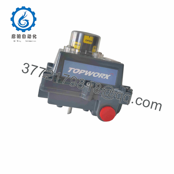
DXP-L21ZNEB
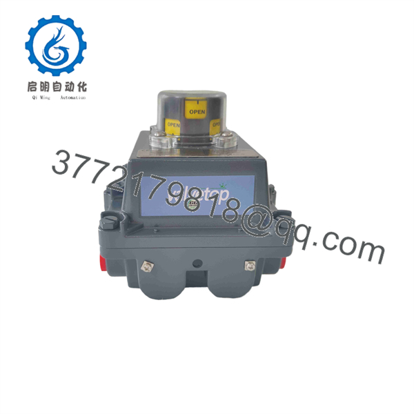
DXP-L21ZNEB
Installation & Configuration Guide
Stage 1: Pre-Installation Preparation — Allow 10–15 Minutes
⚠️ Safety First: Treat this device as hazardous-area equipment. Obtain the required work permit, place the process in a safe state, isolate electrical and pneumatic energy as applicable, and follow the site’s lockout/tagout procedure. Do not open the enclosure in a hazardous atmosphere unless the applicable area classification and equipment certification permit the work.
Tools Required:
- ESD wrist strap
- Appropriate screwdrivers
- Calibrated multimeter
- Wire labels
- Torque-controlled screwdriver suitable for the installed terminals
- Smartphone or camera for configuration photographs
- Appropriate conduit tools and sealing hardware
Before removing the old unit:
- Record the complete model and suffix. Do not substitute a similar-looking DXP variant.
- Photograph the complete installed controller.
- Photograph the switch wiring and terminal arrangement.
- Photograph the position-indicator orientation.
- Record the valve’s OPEN and CLOSED mechanical positions.
- Record the PLC/DCS input channel associated with each GO Switch.
- Record the hazardous-area installation details, including conduit type and cable gland/sealing arrangement.
- Confirm that the replacement has the same sensor configuration and mechanical interface.
The DXP- is specifically configured with two GO Switches. A replacement carrying a different DXP suffix can have different sensor, conduit, shaft, or pilot-valve arrangements.
Stage 2: Removing the Old Controller — Allow 10 Minutes
- Verify electrical and process isolation.
- Remove the enclosure cover according to the applicable TopWorx installation procedure.
- Label each field conductor before disconnecting it.
- Photograph the wiring again after labels are installed.
- Disconnect the switch wiring without pulling on the conductors.
- Release the mechanical mounting hardware.
- Remove the controller without forcing the valve stem or actuator shaft.
- Inspect the actuator mounting bracket, shaft coupling, and mounting surface.
- Check for corrosion, damaged threads, contaminated seals, or mechanical play.
⚠️ Do not discard the old controller yet. Keep it beside the replacement until valve-position feedback has been proven from the DCS or PLC.
Stage 3: Installi — Allow 10–20 Minutes
- Verify the full part n.
- Compare the replacement physically with the removed unit.
- Confirm the two GO Switch configuration.
- Confirm the NAMUR shaft arrangement.
- Confirm the two 3/4-inch NPT conduit entries.
- Confirm that the mounting bracket and actuator interface match.
- Install the controller onto the actuator.
- Align the shaft so the visual indicator correctly represents the actual valve position.
- Adjust the GO Switch positions using the specified cam mechanism.
- Reconnect field wiring according to the recorded terminal arrangement.
- Tighten connections to the applicable manufacturer’s torque specification.
- Verify that conduit entries and sealing arrangements maintain the required hazardous-area protection.
Mechanical self-check:
- C suffix
- Two GO Switches confirmed
- NAMUR shaft correctly engaged
- OPEN indication matches actual valve position
- CLOSED indication matches actual valve position
- Wiring matches the original installation
- Conduit entries correctly sealed
- Enclosure fully secured
Stage 4: Power-On & Functional Testing — Allow 10–15 Minutes
- Complete a continuity and wiring check before energization.
- Energize the associated control circuit according to the site procedure.
- Slowly stroke the valve through the required operating range.
- Confirm the physical visual indicator.
- Confirm the OPEN GO Switch changes state at the intended position.
- Confirm the CLOSED GO Switch changes state at the intended position.
- Monitor the corresponding PLC/DCS discrete inputs.
- Verify that the control-system indication agrees with the physical valve position.
- Repeat the valve stroke several times.
- Check that neither switch chatters near its operating point.
⚠️ Do not assume a correct visual indicator means correct electrical feedback. provides discrete switch outputs; prove both electrical states at the receiving PLC/DCS input.
Troubleshooting checks:
- Valve indication reversed: Check shaft orientation and switch cam adjustment.
- One switch does not change state: Check the corresponding GO Switch wiring and mechanical cam position.
- Both inputs remain unchanged: Check the control-system input circuit, common/reference wiring, and field cable continuity.
- Intermittent feedback: Inspect mechanical alignment, terminal connections, cable strain, and switch adjustment.
- Mechanical mismatch: Stop installation and verify the actuator bracket, shaft, and NAMUR interface rather than forcing the assembly.
Supplier QC / Acceptance Procedure
For a surplus or replacement unit, the inspection record should distinguish what was actually tested from what was only visually inspected.
1. Inbound Inspection & Traceability
- Record manufacturer, full part number, and serial number.
- Verify OEM packaging and available traceability documents.
- Inspect for corrosion, impact damage, machining damage, and enclosure deformation.
- Check the shaft, enclosure threads, conduit entries, and sealing surfaces.
- Confirm that the supplied configuration m.
2. Functional Testing
- Verify both GO Switches independently.
- Confirm SPDT contact operation with a calibrated multimeter.
- Exercise the switching mechanism repeatedly.
- Verify OPEN/CLOSED indication against the mechanical position.
- Record test results on a formal inspection sheet.
3. Electrical Testing
- Verify contact continuity and switching behavior.
- Check for unintended shorts between applicable terminals.
- Perform insulation testing only when the test voltage is appropriate for the specific installed components and manufacturer instructions permit it.
4. Configuration Verification
- Record the complete model suffix.
- Photograph the internal and external configuration where permitted.
- Record switch wiring and mechanical adjustment.
- Preserve the test record with the serial number.
5. Final QC & Packaging
- Inspector sign-off.
- ESD protection where applicable.
- Protect the shaft and enclosure during shipment.
- Use heavy-duty corrugated packaging.
- Mark the package with the part number and QC date.
Transparency note: Do not claim a 24-hour load test, factory seal status, or specific certification status for an individual piece of stock unless the supplier has actually verified and documented it. Test photographs and the completed inspection report should be available to the buyer on request.
Frequently Asked Questions (FAQ)
C be hot-swapped?
Do not treat it as a hot-swappable PLC I/O modul is a field-mounted discrete valve controller with hazardous-area certification. Isolate the relevant electrical and process energy and follow the site’s hazardous-area work procedure before opening or replacing the device.
What exactly does the “” suffix specify?
The suffix is important. The published configuration identifies DXP as the enclosure, L2 as two GO Switches, 1 as the hazardous-area classification configuration, Z as the visual-display option, N as the NAMUR 316 stainless-steel shaft, E as two 3/4-inch NPT conduit entries, and B as Buna-N O-rings.
a valve positioner?
Technically, calling it a conventional valve positioner is misleading. This configuration is a discrete valve controller/switchbox that uses two GO Switches to provide valve-position feedback. It is not the same type of device as a pneumatic or digital modulating positioner that continuously controls valve travel.
provide a 4–20 mA output?
The exact configuration should not be specified as a 4–20 mA transmitter. The published configuration identifies two SPDT GO Switches. Some online reseller pages incorrectly combine generic DXP-series specifications with this exact model. For replacement work, use the model-specific configuration rather than a generic DXP description.
suitable for hazardous areas?
The published configuration specifies explosion-proof/flameproof applications, including Class I Division 1/2 classifications and a Zone 1 Ex d configuration. The drawing also references SIRA 07ATEX1273X and IECEx SIR 07.0093X. Always verify the certification marking on the actual unit against the site’s hazardous-area classification before installation.
What should I check before ordering a replacement?
Match more than the first part of the model number. Verify , two GO Switches, NAMUR shaft, two 3/4-inch NPT entries, hazardous-area certification, enclosure material, and O-ring specification. A DXP unit with a different suffix may look nearly identical while having a different sensor or mechanical configuration.
Is this model obsolete?
I found current distributor and product listin, but availability is inconsistent. One current listing shows the exact part as out of stock with an estimated 12-week lead time, while another distributor listing reports zero stock. That means buyers should confirm actual physical stock, condition, serial number, and lead time rather than assuming that an online “in stock” label represents confirmed inventory.
Why might a s cost less than a factory-sourced unit?
Pricing can differ because surplus inventory, distributor stock, factory-new stock, and refurbished units have different acquisition costs and warranty arrangements. Do not judge condition from price alone. For procurement, request photographs of the actual unit, the nameplate, serial number, packaging, and—if the unit is used or surplus—a documented functional test.



