
 WhatsApp: +86 16626708626
 Email:
  Phone: +86 16626708626
Description
Key Technical Specifications
| Parameter | Value |
|---|---|
| Manufacturer | Triconex |
| Model | 3664 |
| Module Type | Dual Digital Output (DDO) |
| Nominal Voltage | 24 VDC |
| Recommended Voltage Range | 16–30 VDC |
| Maximum Voltage | 36 VDC |
| Output Signals | 32, commoned |
| Output Configuration | Dual, serial |
| Maximum Current | 2 A per point |
| Surge Current | 10 A for 10 ms |
| Logic Power | <10 W |
| Load Leakage Current | 2 mA maximum |
| Typical Voltage Drop | <1.5 VDC |
| Point Isolation | 1,500 VDC minimum |
| Status Indicators | Individual On/Off; PASS, FAULT, ACTIVE |
| Field Interface | External termination panel required |
| Color Code | Dark blue |
| Recommended Safety Application | De-energize-to-trip |
The 3664 is specifically documented as a 32-point Dual Digital Output module with a nominal 24 VDC supply. The published Tricon documentation specifies 16–30 VDC operation, 36 VDC maximum voltage, 2 A maximum per output point, and 1,500 VDC minimum point isolation.
⚠️ Important safety limitation: Tricon documentation states that Models 3664 and 3674 are not recommended for energize-to-trip applications, because certain hardware faults can cause an output to remain Off/de-energized. The 3664 is intended for applications where the safety philosophy is compatible with this behavior.
Product Introduction
The TRICONEX 3664 is a 32-point Dual Digital Output (DDO) module for Tricon safety control systems. It operates from a nominal 24 VDC field supply and provides commoned digital outputs for interfacing the Tricon controller with final control elements and other discrete field devices.
Its dual, serial architecture is intended for de-energize-to-trip control programs. The module provides per-point status indication, output diagnostics, self-protection against over-voltage, over-temperature, and over-current, and requires an external termination panel for field connections.
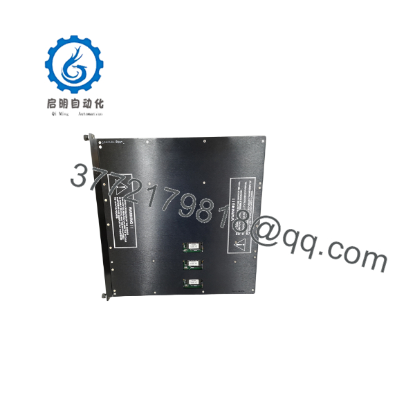
3664
Installation & Configuration Guide
Stage 1: Pre-Installation Preparation — Approximately 10 Minutes
⚠️ Safety First: A Triconex 3664 can form part of a safety instrumented system. Do not treat this replacement like an ordinary PLC I/O swap. Obtain operations approval, place the process in the approved safe state, follow the site’s lockout/tagout procedure, and implement the approved SIS bypass procedure before removing a protection channel.
Tools Required:
- ESD wrist strap
- Appropriate screwdriver
- Calibrated digital multimeter
- Wire labels
- Smartphone or camera
- Approved Tricon configuration/diagnostic workstation
- Current Tricon system configuration and application documentation
Data Backup:
- Record the complete module identification.
- Photograph the 3664 front panel and installed rack.
- Record the module’s chassis slot.
- Photograph the external termination panel (ETP) connections.
- Record every output channel assignment.
- Record the field device connected to each channel.
- Document the existing Tricon system configuration.
- Record current diagnostic status.
- Verify the installed Tricon system version before ordering the replacement.
⚠️ Do not assume that every blue Tricon I/O module is interchangeable. The 3664 is specifically a DDO module. Verify the complete model number and system configuration.
Stage 2: Removing the Old Module — Approximately 5 Minutes
- Confirm the approved process shutdown or bypass condition.
- Verify that the relevant safety function is properly managed before disconnecting the module.
- Follow the Tricon maintenance procedure for module removal.
- Identify and document the 3664 slot.
- Confirm field wiring and termination-panel identification.
- Release the module’s retention mechanism.
- Remove the module straight from the chassis.
- Inspect the mating connector for contamination, damage, or bent contacts.
- Place the removed module in an ESD-safe container.
⚠️ Do not disconnect a safety output channel without confirming what final element it controls. A digital output may operate a shutdown valve, solenoid, relay, motor contactor, or another safety-related device.
Stage 3: Installing the New Module — Approximately 5–10 Minutes
- Verify the replacement model is 3664.
- Compare the module label and hardware identification with the removed unit.
- Confirm the module is intended for the same Tricon system generation.
- Put on the grounded ESD strap.
- Check the chassis connector.
- Insert the module into the correct keyed position.
- Confirm that the mechanical retention mechanism engages.
- Reconnect the associated system/termination-panel cable.
- Verify the external termination-panel wiring against the approved drawings.
- Confirm the field power supply is within the specified 16–30 VDC operating range.
Configuration Clone — Critical
Before returning the module to service:
- Verify the 32 output channel assignments.
- Confirm each output’s intended field device.
- Verify the approved de-energize-to-trip philosophy.
- Review the Tricon configuration.
- Check module diagnostic status.
- Confirm the external termination-panel wiring.
- Verify field supply polarity and voltage.
- Confirm output behavior through the approved commissioning procedure.
- Verify the safety logic and trip path.
- Document the replacement in the plant maintenance records.
Self-Checklist:
- Model 3664 verified
- Correct Tricon chassis position
- Correct system generation
- ESD precautions followed
- ETP cable secure
- Field wiring verified
- 24 VDC supply verified
- Channel assignments verified
- Safety logic checked
- Diagnostic status normal
Stage 4: Power-On & Testing — Approximately 10–20 Minutes
- Inspect the complete installation before applying power.
- Verify field supply voltage.
- Energize the Tricon system according to the approved maintenance procedure.
- Observe the module’s PASS, FAULT, and ACTIVE indicators.
- Verify individual output status indicators.
- Check the Tricon diagnostic interface for module faults.
- Confirm the module is recognized in the correct chassis position.
- Verify each output channel against the approved configuration.
- Perform a controlled output test where permitted by the SIS test procedure.
- Confirm the final control elements respond correctly.
- Verify the complete shutdown path.
- Remove any maintenance bypass only after the approved functional test passes.
The Tricon documentation identifies PASS, FAULT, and ACTIVE as module status indicators, with individual On/Off indication for the output points.
Quality-Control Procedure for Replacement Inventory
1. Inbound Inspection & Traceability
- Verify the 3664 model marking.
- Record available serial and revision information.
- Inspect the housing and connector areas.
- Check for corrosion, mechanical damage, contamination, or evidence of rework.
- Photograph the actual module.
- Verify supplied documentation where applicable.
2. Functional Testing
Use a known-good Tricon test rack or an approved equivalent test environment appropriate to the module and system generation.
- Verify power-up behavior.
- Check PASS/FAULT/ACTIVE indications.
- Verify module recognition.
- Exercise output channels using an approved test fixture.
- Verify output switching behavior.
- Check diagnostic reporting.
- Generate a test report for the individual unit.
Do not state that a unit passed a 24-hour load test unless that test was actually performed on that specific unit.
3. Electrical Testing
Where the manufacturer’s procedure permits:
- Verify supply voltage.
- Check output switching.
- Verify continuity where appropriate.
- Confirm field-side isolation using an approved procedure.
⚠️ Do not apply arbitrary hipot or Megger voltages to the electronic module. The documented 1,500 VDC point-isolation rating does not mean a technician should indiscriminately apply a 1,500 VDC insulation test to an assembled electronic PCB. Use the manufacturer’s approved test procedure.
4. Configuration Verification
- Record module identification.
- Record hardware revision where available.
- Verify system compatibility.
- Document test configuration.
- Preserve the original module for comparison.
5. Final QC & Packaging
- QC inspection sign-off
- ESD-safe packaging
- Connector protection
- Anti-static bag
- Shock-resistant packaging
- Individual unit identification
- Test report when testing was actually performed
Test photographs and videos should be available upon request when they were actually recorded for the supplied unit.
Frequently Asked Questions (FAQ)
What type of module is the TRICONEX 3664?
The 3664 is a Dual Digital Output (DDO) module, not an analog output module. It provides 32 commoned digital output signals and operates at a nominal 24 VDC.
Some third-party listings incorrectly describe the 3664 as an analog output or generic PLC module. For procurement, rely on the Tricon system documentation and the physical model marking rather than a reseller’s generic product description.
Can the 3664 be hot-swapped?
Tricon documentation states that DDO modules support hot-spare capability, allowing online replacement of a faulty module in an appropriately configured system. The modules are mechanically keyed to prevent incorrect installation.
However, “hot-spare capability” should not be interpreted as permission to remove a module without checking the specific Tricon architecture, configuration, safety procedure, and operating state. Follow the approved maintenance procedure for the installed system.
Is the 3664 suitable for an energize-to-trip safety application?
No. Do not select it for an energize-to-trip application without an engineering review. Tricon documentation specifically states that Models 3664 and 3674 are not recommended for energize-to-trip applications because certain hardware faults can leave outputs de-energized.
The module is documented for de-energize-to-trip control programs.
What voltage does the 3664 use?
The nominal voltage is 24 VDC. The documented recommended operating range is 16–30 VDC, with a 36 VDC maximum.
Do not use a generic “24 VDC” description as permission to exceed the specified range.
How much current can each output handle?
The documented maximum is 2 A per point, with a 10 A surge rating for 10 ms. Load leakage is specified at a maximum of 2 mA.
The actual field load must still be evaluated against the complete termination-panel, wiring, power-supply, and application requirements.
Does the 3664 connect directly to field wiring?
The Tricon documentation states that DDO modules require a separate external termination panel (ETP) with a cable interface to the Tricon backplane. The digital outputs source current to field devices, and field power must be wired to each output point at the field termination.
Therefore, verify the exact ETP and system cable before ordering a replacement.
Is the TRICONEX 3664 obsolete?
The 3664 is legacy Tricon hardware. A published Tricon lifecycle document lists the 3664 as a 24 VDC, 32-point dual digital output module, with lifecycle dates indicating a transition beyond the preferred/available phases.
For a production SIS, do not base a lifecycle decision solely on surplus availability. Check the installed Tricon version, current OEM lifecycle information, spare strategy, and migration requirements.
What should I provide when ordering a replacement 3664?
Provide:
- Model: 3664
- Tricon system generation
- Chassis information
- Module slot
- Hardware revision
- Serial number, if available
- Termination-panel model
- System cable information
- Required condition: New Original / New Surplus or Refurbished / Tested
- Existing application documentation
For a safety-related replacement, confirm the complete configuration before purchase. A module with the correct 3664 model number but an incompatible system configuration can still create commissioning problems.



