
 WhatsApp: +86 16626708626
 Email:
  Phone: +86 16626708626
Description
Key Technical Specifications
- Manufacturer: Triconex, a Schneider Electric safety-system brand
- Part Number: 4000212-020
- Alternative Search Format: 4000212020
- Product Type: Cable assembly / cable and wire
- Functional Description: I/O communication bus cable
- System Family: Tricon safety instrumented system
- Primary Use: Communication interconnection within a Tricon I/O system
- Connector Configuration: Must match the existing cable before replacement
- Reported Weight: Approximately 0.34 kg
- Installation Environment: Tricon control or I/O cabinet
- Handling Requirement: ESD-aware handling and strain-relieved routing
- Replacement Requirement: Match the complete part number; do not substitute a different 4000212 suffix without confirming cable pinout and length
Distributor listings identify 4000212-020 as a Triconex cable assembly specifically described as an “I/O COMM BUS” cable. A conflicting third-party listing describes it as a processor module; that claim conflicts with multiple cable-specific distributor records and should not be used for procurement or installation decisions.
Product Introduction
The Triconex 4000212-020 is an I/O communication bus cable assembly for Tricon safety instrumented systems. It provides the physical interconnection required for data communication among the applicable Tricon I/O bus components and associated cabinet hardware. It is not a CPU, I/O module, or field termination assembly.
This part is typically purchased as an exact spare for a damaged, missing, or degraded installed cable. The correct replacement decision depends on the complete part number, cable length, connector keying, pin count, shielding arrangement, and installed routing. For a safety system, do not replace it with a visually similar communication cable unless the OEM documentation confirms identical electrical and mechanical compatibility.
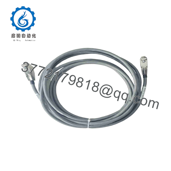
4000212-020
Troubleshooting Quick Reference
| Symptom | Possible Cause | Relevance to This Part | Quick Check Method | Recommendation |
|---|---|---|---|---|
| I/O communication fault after maintenance | Cable connector not fully latched, bent contact, wrong cable routing | ✅ High | With power isolated under the site safety procedure, inspect both cable ends for correct keying, full engagement, pin damage, and latch condition | Reseat the original cable and inspect connector faces before replacement |
| Intermittent I/O communication alarms | Broken conductor, cable strain, vibration damage, poor connector contact | ✅ High | Review event-log timestamps, gently inspect for movement-related faults during an approved outage, and check for crushed or sharply bent cable sections | Replace the cable if continuity or connector retention is questionable |
| No communication to an I/O area | Failed I/O module, failed chassis interface, power loss, cable open circuit | ⚠️ Medium | Check rack power and module diagnostic indicators first; then isolate the system correctly and test end-to-end conductor continuity against the approved wiring documentation | Do not replace the cable until power, module status, and connector seating are verified |
| Fault begins immediately after cable replacement | Incorrect suffix, connector mismatch, cable installed reversed, damaged mating connector | ✅ High | Compare the removed cable and replacement side by side: part number, length, plug keying, pin count, shielding, and labeling | Stop commissioning and reinstall the verified original cable if safe to do so |
| Recurrent communication faults during high vibration | Inadequate strain relief, cable rubbing against cabinet hardware, compromised connector latch | ✅ High | Inspect cable clamps, bend radius, cabinet-door clearance, and movement near connectors | Route with approved strain relief and replace any cable with damaged insulation or latch hardware |
| Controller reports fault but all I/O looks normal | Transient electrical noise, grounding issue, intermittent bus event, controller diagnostic setting | ❌ Low to Medium | Review Tricon diagnostics, cabinet bonding, shield termination, and event history before disturbing the cable | Investigate grounding and diagnostics; the cable is only one possible source |
| Cable jacket is discolored, cracked, or cut | Age, heat exposure, chemical exposure, abrasion, or improper cabinet routing | ✅ High | Visually inspect the full accessible cable length under proper isolation conditions | Replace the cable; do not tape over damaged insulation inside a safety-system cabinet |
Field warning: Communication cable faults can imitate failed I/O modules. Start with the simple checks: rack power, module diagnostic LEDs, cable seating, and connector-pin condition. Replacing a cable before checking those items can create unnecessary downtime and introduce a new fault.
❗ Exact suffix matters: Do not assume 4000212-006, 4000212-010, and 4000212-020 are interchangeable. The shared base number identifies a cable family, but the suffix can represent a different assembly length, connector arrangement, or intended location. One common mistake is ordering a cable that looks correct in a listing photo, then finding it will not route or key correctly at the cabinet.
❗ Connector inspection comes first: Take photos before disconnecting the old cable. Photograph plug orientation, labels, cable routing, clamps, shield connection, and any cabinet annotations. It sounds basic, but a reversed routing path or missed strain-relief clamp can create intermittent faults that waste a shift.
❗ Do not force a connector: If a Tricon cable plug does not seat with normal hand pressure, stop. Verify part number, mating hardware, and alignment. Forcing it can bend contacts or damage an expensive chassis-side connector.
❗ Power and safety procedure: Follow the site-approved proof-test, bypass-management, and lockout/tagout procedure. This cable belongs to a safety-instrumented-system environment. A communication interruption can initiate diagnostics, alarms, bypass conditions, or a process trip depending on system design.
❗ ESD and cabinet housekeeping: Use a grounded wrist strap when working near Tricon electronic assemblies. Keep the cable away from sharp sheet-metal edges, high-current conductors, and moving cabinet parts. Do not add an unapproved cable tie directly over a connector boot or strain-relief point.
Keep these checks in mind and you will save yourself 90% of typical rework time. If the fault remains unresolved, provide photos of both cable ends, the full cable label, affected Tricon diagnostics, and the rack/module LED states to technical support.
Frequently Asked Questions
What is the Triconex 4000212-020 used for?
The Triconex 4000212-020 is an I/O communication bus cable assembly used within the Tricon safety-system environment. Distributor records describe it as a cable and wire product with the function “I/O COMM BUS.” It supports the communication interconnection of the applicable system components; it is not a Tricon processor or I/O card.
Is 4000212-020 a Triconex CPU module?
No. Multiple cable-specific distributor listings identify 4000212-020 as an I/O communication bus cable. One third-party product page incorrectly labels it a main processor module and includes generic Tricon CPU specifications that conflict with the cable records. Use the OEM manual and the installed assembly label, not that conflicting listing, for safety-system maintenance.
Can I substitute 4000212-006 or 4000212-010 for 4000212-020?
Do not substitute based on appearance or the shared 4000212 prefix. Other suffixes are separately listed as communication cable assemblies, which strongly indicates that the suffix identifies a distinct cable variant. Confirm exact length, connector type, pinout, shielding, cable routing, and approved Tricon documentation before approving an alternate.
Can I replace the cable while the Tricon system is powered?
Do not assume live replacement is permitted. Treat this as a safety-system maintenance task and follow the plant’s approved work package, bypass-management rules, proof-test requirements, and lockout/tagout procedure. Disconnecting an active I/O communication cable can generate diagnostics, communication failures, and potentially process consequences.
How do I confirm I have the correct cable before ordering?
Match the complete label: 4000212-020. Then compare the removed cable’s overall length, connector ends, keying, pin count, orientation, shielding, strain-relief features, and routing path. Send photographs of both ends and any cable tags before purchase if the installed unit is damaged or unreadable.
Is the Triconex 4000212-020 obsolete?
Treat it as a legacy spare with potentially limited availability. Current market records show it primarily through independent industrial distributors and surplus channels, rather than as a routine new-production item. Procurement should verify actual stock, condition, lead time, and traceability for the exact offered unit.
Why might New Surplus inventory cost less than factory supply?
New Surplus stock usually comes from unused project inventory, cancelled projects, warehouse liquidation, or legacy maintenance stores. It may be new without factory packaging rather than factory sealed. Lower cost does not prove a problem, but it does make inspection important: verify the label, connector condition, cable jacket, storage history, and return or warranty terms before purchasing.
What quality checks should a supplier perform?
For a cable assembly, request practical, documented checks rather than vague claims:
- Confirm the exact 4000212-020 label and photograph both cable ends.
- Inspect the jacket for cuts, cracks, flattening, chemical damage, and UV discoloration.
- Inspect connector housings, keys, latches, pins, and strain-relief points under magnification.
- Perform continuity testing conductor-to-conductor using a calibrated multimeter.
- Check for unintended shorts between conductors and shield paths where applicable.
- Verify continuity to the shield/drain wire only against the approved assembly specification.
- Package in an ESD-safe bag where required, with protective caps or cushioning on connectors.
- Provide the inspection record, packing photos, warranty terms, and actual stock photographs before shipment.



