
 WhatsApp: +86 16626708626
 Email:
  Phone: +86 16626708626
Description
Key Technical Specifications
| Parameter | Value |
|---|---|
| Manufacturer | ICS Triplex / Rockwell Automation |
| Brand Family | Triconex / Trusted |
| Model | 9662-610 |
| Product Type | TMR Digital Output Module |
| I/O Type | Digital Output |
| Number of Outputs | 40 |
| Nominal Field Voltage | 24 VDC |
| Architecture | Triple Modular Redundant (TMR) |
| Safety Platform | Trusted |
| Output Application | Safety-related digital field outputs |
| Typical Uses | ESD, shutdown logic, interlocks, process control |
| Installation | Trusted controller chassis |
| Diagnostics | Module and channel diagnostics |
| Configuration | Trusted system configuration |
| Lifecycle | Legacy; verify exact OEM status |
⚠️ Part-number verification is important: Do not purchase a 9662-610 based solely on a generic “Triconex output module” description. Verify the complete module label, hardware revision, chassis compatibility, and termination arrangement against the installed system.
Product Introduction
The Triconex 9662-610 is a Trusted TMR digital output module associated with the ICS Triplex safety-system platform. It provides redundant digital output control for safety-related applications where the output path must be monitored and fault conditions detected.
For replacement work, the electrical interface is only part of the compatibility check. Engineers should verify the Trusted chassis, TMR architecture, termination assembly, field voltage, output assignment, and application configuration before installing a replacement module.
Installation & Configuration Guide
Stage 1: Pre-Installation Preparation — Approximately 10 Minutes
⚠️ Safety First: The 9662-610 may control safety-critical final elements. Obtain the required maintenance permit, notify operations, place the process in the approved safe state, and follow the site’s lockout/tagout and SIS bypass procedures.
Tools Required:
- ESD wrist strap
- Appropriate screwdriver
- Calibrated digital multimeter
- Wire labels
- Smartphone or camera
- Approved Trusted engineering workstation
- Current application backup
- Site-approved test equipment
Data Backup:
- Record the complete 9662-610 catalog number.
- Photograph the module label and hardware markings.
- Photograph the complete chassis.
- Record the module slot.
- Photograph the termination assembly.
- Document every output channel and connected field device.
- Save the current Trusted application.
- Record the current module diagnostics.
- Document active overrides or bypasses.
- Verify the approved I/O schedule.
⚠️ Do not remove the module until you know what each output controls. An output channel may operate a shutdown solenoid, motor contactor, valve, alarm, or another final control element.
Stage 2: Removing the Old Module — Approximately 5 Minutes
- Confirm the process is in the approved maintenance state.
- Verify required SIS bypasses are active and documented.
- Confirm the correct chassis slot.
- Photograph the installed module.
- Confirm the output termination identification.
- Release the module retention mechanism.
- Remove the module straight from the chassis.
- Inspect the backplane connector.
- Check for contamination or damaged contacts.
- Place the removed module in an ESD-safe package.
⚠️ Do not disturb adjacent redundant modules unnecessarily. Accurate slot identification is critical in a TMR architecture.
Keep the original module until the replacement passes diagnostics and the required functional test.
Stage 3: Installing the New Module — Approximately 5–10 Minutes
- Verify the replacement is exactly 9662-610.
- Compare the replacement label with the removed module.
- Confirm the correct Trusted chassis position.
- Verify the associated termination assembly.
- Attach a grounded ESD wrist strap.
- Inspect the module connector.
- Align the module with the chassis guides.
- Insert it without forcing the connector.
- Engage the retention mechanism.
- Confirm that the module is fully seated.
- Verify the field termination connection.
- Confirm output wiring remains correctly identified.
Configuration Clone — Critical
Restore the approved configuration rather than rebuilding the output mapping from memory.
Verify:
- Module slot
- Module type
- Output channel assignments
- Field-device destinations
- Normal output states
- Shutdown states
- Voting configuration
- Diagnostics
- Application tags
- Interlock logic
- Maintenance overrides
- Termination arrangement
Self-Checklist:
- 9662-610 verified
- Correct Trusted chassis
- Correct slot
- TMR architecture confirmed
- Termination assembly verified
- Output mapping backed up
- Module seated correctly
- Application configuration backed up
- Overrides documented
- Field devices identified
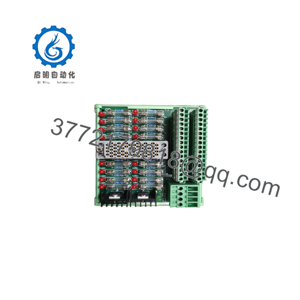
9662-610
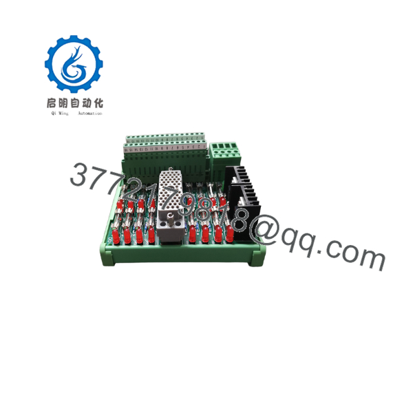
9662-610
Stage 4: Power-On & Testing — Approximately 10–30 Minutes
- Complete a visual inspection before restoring the module.
- Restore the system according to the approved Trusted maintenance procedure.
- Observe module status indicators.
- Check the engineering workstation for module faults.
- Confirm the 9662-610 is recognized in the correct slot.
- Verify module health.
- Review channel diagnostics.
- Verify field supply voltage.
- Perform the approved output-channel test.
- Confirm the associated final control element responds correctly.
- Verify shutdown and interlock behavior.
- Confirm no unexpected diagnostic faults remain.
- Remove maintenance bypasses only after the approved functional test.
- Record the completed test results.
⚠️ Do not test a safety output by randomly forcing channels. Use the plant’s approved proof-test procedure. The objective is to verify the complete signal path, not merely illuminate an output indicator.
Technical Pitfalls and Survival Guide
1. Trusted vs. Tricon Platform Confusion
❗ The terminology surrounding Triconex, Trusted, and ICS Triplex can cause procurement errors. Confirm the actual installed platform before ordering.
A module number should never be matched by catalog-number similarity alone.
2. Output Mapping
A replacement can pass a hardware diagnostic while still being incorrectly configured.
Before removal, document the relationship between each output channel and its final control element.
3. Field Voltage
Verify the actual field supply voltage and load requirements. Do not assume that every 24 VDC field device presents the same electrical load.
Check the complete circuit, including protection and termination components.
4. TMR Architecture
The redundant architecture is part of the safety design. Do not replace the module with a conventional PLC output card or another visually similar I/O module.
5. Application Revision
Record the running application and configuration version before maintenance. A hardware replacement should not be allowed to introduce an undocumented configuration change.
Frequently Asked Questions (FAQ)
What is the Triconex 9662-610?
The Triconex 9662-610 is identified with the Trusted TMR digital-output architecture associated with ICS Triplex safety systems. It is intended for safety-related digital output functions rather than ordinary PLC applications.
Is the 9662-610 a standard 24 VDC output card?
It should not be treated as a generic 24 VDC PLC output card. The module operates within a Trusted TMR safety architecture, so chassis, termination, configuration, diagnostics, and voting arrangements all matter.
Can I hot-swap the 9662-610?
Do not assume that it can be removed under power. Whether online replacement is permitted depends on the Trusted system architecture, application, site procedures, and safety-function requirements.
For an operating safety system, follow the approved Trusted maintenance procedure rather than a generic PLC hot-swap procedure.
Will replacing the 9662-610 erase the safety application?
The physical module replacement does not inherently erase the application running in the controller. However, you should make a verified application backup before starting.
After installation, confirm that the controller recognizes the replacement module in the correct position and that the output configuration matches the approved application.
What should I check before buying a replacement?
Provide the supplier with:
- Exact model: 9662-610
- Complete nameplate information
- Hardware revision
- Trusted chassis type
- Module slot
- Field voltage
- Termination assembly
- Application/configuration version
- Required condition
For a safety-system spare, request photographs of the actual unit rather than relying only on a stock photograph.
Is the 9662-610 obsolete?
Treat the 9662-610 as legacy safety-system hardware and verify the current OEM lifecycle status before planning long-term inventory.
If the plant depends on this module, maintaining an appropriately tested spare can reduce the risk of an extended outage caused by an unexpected hardware failure.
Should I buy New Original or Refurbished?
For a safety-critical spare, New Original / New Surplus is generally the preferred condition when traceable stock is available.
A refurbished module can be considered when properly documented, but request the actual test scope, module photographs, serial/label information, and hardware revision. A generic “tested” claim is not enough for a safety-system replacement.
What is the correct replacement for a failed 9662-610?
Do not select a replacement based only on the model number. Verify the complete 9662-610 ordering information against the installed Trusted system and its approved configuration.
If the exact module is unavailable, a migration or substitute decision should be treated as an engineering change, not a simple spare-parts substitution.



