
 WhatsApp: +86 16626708626
 Email:
  Phone: +86 16626708626
Description
Key Technical Specifications
| Parameter | Value |
|---|---|
| Manufacturer | Triconex / Schneider Electric |
| Model | CM01 |
| Module Type | Communication Module |
| System Family | Tricon / Triconex |
| Primary Function | Controller-to-host and device communications |
| Serial Communications | Modbus-capable serial communications on applicable CM generations |
| Network Communications | Ethernet networking on applicable Tricon communication modules |
| Protocols | Modbus, TriStation, TSAA, peer-to-peer on applicable generations |
| Serial Interface | RS-232 / RS-485 on applicable CM designs |
| Network Speed | Generation-dependent; older Tricon/Trident CM documentation specifies 10 Mbps and 100 Mbps Ethernet interfaces |
| Configuration Software | TriStation family, depending on Tricon platform and firmware |
| System Compatibility | Must match the installed Tricon chassis, module generation, and firmware |
| Safety Application | Tricon safety and critical-control architectures |
| Firmware | Revision must be checked against the installed controller configuration |
| Environmental Rating | Verify against the exact OEM hardware revision before installation |
For reference, published Trident CM documentation describes three optically isolated RS-232/RS-485 serial ports, selectable transmission rates up to 115.2 kbps per port, and 10/100 Mbps Ethernet interfaces. It also lists Modbus, TriStation, TSAA, peer-to-peer, and time-synchronization functions. These specifications should not be automatically applied to every product sold as “CM01.”
Product Introduction
The Triconex CM01 is identified in the surplus automation market as a Triconex communication module used for communication between a Tricon safety controller and external systems or devices. Tricon communication architectures can provide Modbus, TriStation, Ethernet, and peer-to-peer communications, depending on the hardware generation.
The critical purchasing issue is exact hardware identification. Triconex communication modules are not interchangeable simply because the front-panel designation looks similar. Confirm the complete part number, chassis generation, firmware revision, connectors, and existing communication configuration before ordering.
Installation & Configuration Guide
Stage 1: Pre-Installation Preparation — Approximately 5–10 Minutes
⚠️ Safety First: A Triconex system may perform safety-instrumented or emergency-shutdown functions. Follow the site’s approved maintenance procedure and MOC requirements. Do not remove a communication module from an operating safety system unless the specific Tricon hardware and site procedure explicitly permit online replacement.
Tools Required:
- ESD wrist strap
- PH1 screwdriver where applicable
- Calibrated digital multimeter
- Wire labels
- Smartphone or camera
- Laptop with the appropriate Triconex engineering software
- OEM hardware documentation
Data Backup:
- Record the complete part number and hardware revision from the existing module.
- Photograph the front panel and every connector before removal.
- Record network addresses and communication settings.
- Record serial-port baud rate, parity, station address, and termination settings where applicable.
- Record the installed firmware revision.
- Save the current controller/application configuration before beginning work.
❗ Do not order solely from “CM01.” The Tricon product family contains multiple communication-module generations with different interfaces and system compatibility.
Stage 2: Removing the Old Module — Approximately 5 Minutes
- Place the safety system in the approved maintenance state.
- Follow the site’s LOTO procedure if power removal is required.
- Verify that the module is electrically safe to handle.
- Disconnect communication cables only after documenting their original positions.
- Label each cable before removal.
- Release the module’s mechanical retaining mechanism.
- Pull the module straight out without twisting it.
- Inspect the connector and chassis/backplane for contamination, bent contacts, or mechanical damage.
⚠️ Keep the original module on site until the replacement has passed functional testing. It provides the best reference for connector positions, hardware revision, and configuration.
Stage 3: Installing the Replacement — Approximately 5 Minutes
- Put on the grounded ESD wrist strap.
- Confirm that the replacement’s complete part number and hardware revision match the approved replacement specification.
- Compare the replacement with the old module photograph.
- Verify connector type and position.
- Reproduce applicable communication settings exactly.
- Insert the module straight into the correct slot.
- Engage the retaining mechanism fully.
- Reconnect every communication cable to its original position.
- Check that connectors are fully seated and cable strain is not being transferred to the module.
Self-Checklist:
- Exact part number verified
- Hardware revision verified
- Firmware requirement checked
- Network configuration recorded
- Serial configuration recorded
- Cables returned to original ports
- Module fully seated
- Retaining mechanism locked
Stage 4: Power-On & Testing — Approximately 10 Minutes
- Perform a final visual inspection before energizing the system.
- Verify that no loose conductor or foreign object can contact the chassis.
- Restore power according to the approved site procedure.
- Observe the module status LEDs during initialization.
- Confirm that the module reaches its expected operational state.
- Connect the approved engineering workstation.
- Verify controller/module recognition.
- Check firmware and hardware identification.
- Verify network communication.
- Test the required Modbus, TriStation, or other configured communication paths.
- Confirm data exchange with the receiving system.
- Review diagnostics and event logs.
⚠️ Do not assume a green status LED proves correct application communication. A module can initialize correctly while an IP address, Modbus station address, serial parameters, or firmware compatibility remains incorrect.
Common fault checks:
- No communication: Check cable, port assignment, IP configuration, and network switch configuration.
- Modbus timeout: Check slave address, baud rate, parity, stop bits, and register mapping.
- Module not recognized: Check hardware revision and chassis compatibility.
- Firmware-related fault: Compare the installed firmware with the validated application configuration.
- Intermittent communication: Check shielding, grounding, connectors, and network error counters.
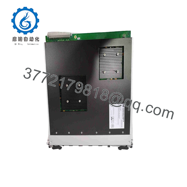
CM01
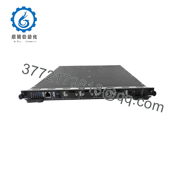
CM01
Frequently Asked Questions (FAQ)
Can the Triconex CM01 be hot-swapped?
Do not assume that it can. Hot replacement depends on the specific Tricon hardware generation and approved system procedure. Some Triconex configurations support online module replacement, while the procedure and restrictions vary by hardware family. Verify the exact OEM manual for the installed chassis before removing the module under power.
Is Triconex CM01 an obsolete model?
The designation requires additional identification before an obsolescence determination can be made. Current Triconex documentation uses specific communication-module model numbers such as the TCM and NCM families. A reseller’s “” description may not represent the OEM ordering number.
What is the direct replacement for ?
There is no technically responsible universal replacement based only on “.” The replacement must match the Tricon chassis generation, communication architecture, connectors, firmware requirements, and application configuration. For example, the documented Tricon TCM is specified for Tricon v10.0 and later, which demonstrates why system version matters.
Will removing the communication module erase my Tricon application logic?
Normally, removing a communication interface module is not the same operation as deleting the controller application. However, communication configuration, aliases, network settings, and application-specific mappings still need to be verified after replacement. Back up the system configuration before beginning the work.
Why does the replacement need the same firmware revision?
Communication behavior can depend on firmware and system generation. A replacement that physically fits the chassis may still fail to communicate correctly if its firmware is outside the validated range. Record the existing firmware before removing the old unit and confirm the acceptable revision with the OEM documentation.
Is a surplus Triconex safe to install?
Condition and compatibility are separate questions. A New Original / New Surplus unit should still be checked for correct part number, hardware revision, storage condition, and functional operation. A refurbished unit should have documented testing and traceability. For safety-system hardware, request the test report and verify the exact hardware identity before installation.
What should I verify before purchasing this module?
At minimum, provide the supplier with a photograph of the existing nameplate and front panel. Confirm the complete part number, hardware revision, chassis type, firmware revision, connector configuration, and required communication protocols. This is much safer than purchasing a module listed only as “Triconex .”
For Tricon communication modules, published documentation confirms that communication capabilities vary by generation, so the full hardware identity matters more than the short “” designation.



