
 WhatsApp: +86 16626708626
 Email:
  Phone: +86 16626708626
Description
Key Technical Specifications
- Manufacturer: Triconex, now part of Schneider Electric’s EcoStruxure Triconex safety-systems portfolio.
- Model Number: DI2301
- Common Product Reference: 2301 DI baseplate
- Associated Part Number: 7400208B-020, reported in aftermarket listings; confirm against the physical label before ordering.
- Product Type: Digital input baseplate / I/O termination baseplate
- System Family: Triconex Trident safety instrumented system
- Primary Use: Field-side interface for Trident 24 V DC digital input circuits
- Nominal Field Voltage: 24 V DC
- Input Channels: 16 independent digital input channels reported by an aftermarket product listing; verify against the installed baseplate documentation.
- Reported Field Input Range: 19.2–30 V DC; this value requires confirmation from an OEM Trident document for the exact installed revision.
- Reported Logic Thresholds: ON at or above 12 V DC; OFF at or below 6 V DC; verify against the exact module/baseplate combination.
- Reported Input Response Time: 5 ms maximum; verify against the approved Triconex documentation for the complete I/O assembly.
- System Architecture: Used with Trident triple modular redundancy safety-system hardware; compatibility depends on the matching I/O module, chassis, and application configuration.
- Field Wiring: Screw-terminal field connections reported by one aftermarket listing; confirm terminal assignment and wire-size limits from the installed unit.
- Lifecycle Status: Legacy safety-system spare part; verify factory support status, revision availability, and traceability before purchase.
Product Introduction
The TRICONEX DI2301 is a 24 V DC digital input baseplate used in the Triconex Trident Safety Instrumented System. It provides the field termination and interface path for discrete safety signals such as emergency-stop contacts, shutdown switches, pressure-switch contacts, valve limit feedback, permissive circuits, and fire-and-gas status signals. An aftermarket listing identifies the associated baseplate reference as 7400208B-020.
The DI2301 is not a general-purpose PLC input card and should not be selected solely by its 24 V DC rating. It must match the installed Trident chassis, the correct digital input module, field terminal arrangement, and validated SIS design. In safety applications, preserve the original wiring segregation, proof-test requirements, and approved change-control process.
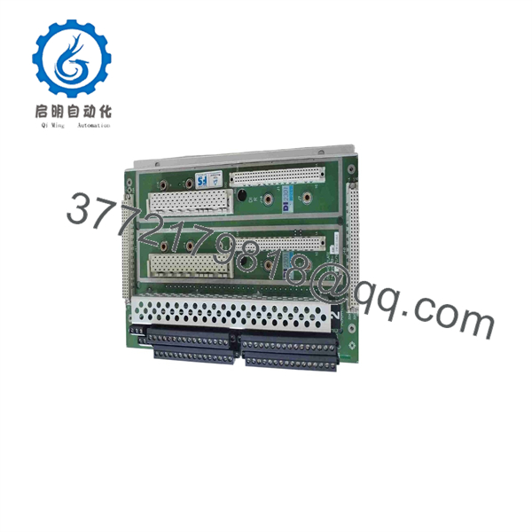
DI2301
Troubleshooting Quick Reference
| Symptom | Possible Cause | Relevance to This Part | Quick Check Method | Recommendation |
|---|---|---|---|---|
| Multiple 24 V DC safety inputs show inactive | Lost 24 V DC field supply, blown fuse, broken common return, loose DI2301 field connection | ⚠️ Medium | Measure the approved field supply at the affected terminal pair and compare with a working channel. Confirm the return/common path using the site wiring drawing. | Repair field power, fuse, or common-return faults before replacing the DI2301. |
| One safety input never changes state | Failed field device, open cable, incorrect input wiring, failed channel, input module fault | ✅ Medium | Measure the input voltage at the exact DI2301 terminal with the device both de-energized and energized. Compare with a known-good channel. | If the correct field voltage reaches the baseplate terminal but the Trident diagnostic remains unchanged, investigate the matching I/O module and baseplate path. |
| Entire input group changes state unexpectedly | Shared supply loss, common-reference problem, damaged multicore cable, terminal block issue | ❌ Usually low | Identify whether affected points share a circuit breaker, fuse, marshalling strip, cable, common return, or field device supply. Check the safety cabinet terminal torque under approved procedures. | Do not replace the baseplate first. Group faults usually originate outside the . |
| Trident reports an I/O module or channel fault after maintenance | Module not fully seated, baseplate connector issue, wrong module/baseplate pairing, damaged chassis connector | ✅ High | Place the unit in the approved maintenance state. Inspect module-to-baseplate engagement, connector pins, chassis slot, and controller diagnostics. | Verify part number and installed slot against the as-built drawings. Never force a module into a mismatched baseplate. |
| Input reads active when the field contact is open | Wiring cross-connection, incorrect wetting voltage reference, leakage current, shorted cable, incorrect terminal assignment | ⚠️ Medium | Isolate the field circuit under permit. Remove the field conductor from the designated terminal and observe whether the input state clears in diagnostics. | If the state remains active with field wiring removed, inspect the baseplate, I/O module, and internal harness. |
| Input status flickers during vibration or cabinet heat-up | Loose terminal, oxidized connector, damaged conductor, intermittent contact, marginal input voltage | ⚠️ Medium | Review event logs for time correlation. Inspect connector retention and terminal condition during a scheduled outage; do not disturb energized safety wiring without authorization. | Correct external connection issues first. Replace only if the fault follows the baseplate after controlled testing. |
| Replacement causes immediate diagnostics | Wrong revision, wrong baseplate type, field wiring moved to incorrect terminals, connector damage, configuration mismatch | ✅ High | De-energize according to the SIS maintenance procedure. Compare old and replacement labels, terminal layout, hardware revision, and all field wiring photographs. | Stop installation until the exact part and terminal mapping are verified by the safety-system owner or qualified SIS engineer. |
| Safety logic trips but physical field devices look normal | Channel configuration issue, forced point, bad field contact, input module diagnostic, logic solver fault | ❌ Low | Check Triconex diagnostic status, force tables, cause-and-effect logic, and the actual field voltage at terminals. | Do not blame the baseplate without checking the SIS application, field device, and matching I/O module. |
| No response after a card or terminal service event | Input module installed incorrectly, plug not seated, bent connector pin, ESD damage | ✅ Medium | Isolate power, inspect the module/baseplate mating faces under good light, verify no pin push-back, then reseat using the approved handling method. | Use a grounded ESD wrist strap and follow the site’s Triconex maintenance procedure. Replace damaged hardware rather than attempting field-level board repair. |
❗ Critical warning: may form part of a safety instrumented function. Never jumper, force, or bypass an emergency shutdown, fire-and-gas, burner-management, or trip input to keep a process running. Changes to SIS hardware, wiring, or configuration require approved management of change, functional checks, and site proof-test procedures.
Take photos of the original label, hardware revision, chassis position, terminal numbering, wire markers, and mating module before removal. It is the most reliable way to prevent a wrong-terminal reconnection at 3:00 AM.
If diagnostics remain unresolved, provide technical support with cabinet photos, and module labels, controller diagnostic logs, as-built loop drawings, terminal voltage readings, and the exact Trident chassis slot.
Frequently Asked Questions
What is the TRICONEX ?
The TRICONEX is identified in aftermarket product information as a Trident 24 V DC digital input baseplate, also referred to as a 2301 DI baseplate. It provides the field-side termination and interface for discrete input signals used in a Triconex Trident safety-system installation.
Is a complete Triconex safety controller?
No. is a baseplate or field-termination component, not the Trident controller or logic solver. It works as part of a complete safety I/O assembly that includes the appropriate chassis, I/O module, field wiring, controller configuration, and validated safety application.
Does handle 24 V DC signals?
Yes. Available product listings describe as a 24 V DC digital input baseplate. One listing reports a 19.2–30 V DC field-input range, but you should verify the permitted voltage range and input thresholds using the official documentation for the exact installed Trident module and hardware revision.
Can I replace with any 24 V DC Triconex input baseplate?
No. Do not substitute based only on voltage or channel count. Confirm the full identifier, associated part number, hardware revision, terminal layout, matching I/O module, chassis family, and field wiring. A wrong baseplate can cause incorrect field termination, channel diagnostics, or loss of a safety function.
Can I hot-swap the baseplate?
No. Treat the as non-hot-swappable unless the exact Triconex installation manual and site-approved maintenance procedure explicitly authorize the activity. A baseplate carries field wiring and serves an SIS application; removal may interrupt safety inputs, create nuisance trips, damage connectors, or leave a protection layer unavailable.
Will replacing erase the Trident application program?
Normally, no. The Trident safety application resides in the controller system rather than the DI baseplate. However, a replacement can still cause safety-system faults if terminal wiring changes, the wrong baseplate revision is installed, the matching I/O module is disturbed, or the system hardware configuration no longer matches the validated design.
Why should I verify the associated number 7400208B-020?
Aftermarket listings associate 7400208B-020 with the TRICONEX 2301 / baseplate, but legacy Triconex hardware can have revision-specific labels, assemblies, and compatible-module requirements. Confirm the exact part number from the existing device label and compare connector layout before ordering.
Why is a New Surplus less expensive than factory inventory?
Legacy SIS components may come from unused plant spares, system upgrades, distributor inventory, or decommissioned assets. The lower price can reflect obsolescence and inventory turnover rather than product quality. For a safety-related part, require exact-unit photos, serial-number traceability where available, label and revision confirmation, written warranty terms, and documented inspection results.
What test evidence should I request before buying a refurbished ?
Request incoming visual inspection records, close photos of all terminals and mating connectors, label and serial-number images, checks for corrosion or rework marks, controlled-fit verification with the compatible Trident I/O module where test hardware is available, and a written QC record. A supplier bench test cannot replace site acceptance testing, functional verification, and the required proof test after installation in a safety instrumented system.



