
 WhatsApp: +86 16626708626
 Email:
  Phone: +86 16626708626
Description
Key Technical Specifications
- Manufacturer: Triconex, part of Schneider Electric’s EcoStruxure Triconex safety-systems portfolio.
- Model Number: DO3201
- Possible Extended Reference: DO3201-A-V001; verify directly from the module nameplate.
- Product Type: Digital output module for safety instrumented system applications.
- Primary System Family: Tricon safety controller platform.
- Safety Architecture: Triple modular redundancy, or TMR, is claimed in several aftermarket product references; verify with official Triconex system documentation before using the module in a safety function.
- Typical Field Supply: 24 V DC is widely reported by aftermarket sources.
- Typical Application: Emergency shutdown, fire-and-gas, burner-management, trip solenoids, shutdown relays, permissive outputs, and alarm outputs.
- Output Type: Discrete DC output; exact sourcing/sinking configuration, channel grouping, and field-terminal interface require confirmation from the correct Triconex manual.
- Output Channel Count: Unverified. Aftermarket listings conflict between 16 and 32 channels, so do not select the module using channel count until the physical label, chassis configuration, and OEM documentation are checked.
- Load Current: Unverified. One source claims 2 A per channel, but this is not sufficiently supported to use for field design.
- Mounting: Tricon rack-mounted module; exact chassis and slot compatibility must be verified.
- Diagnostics: Field-output and module diagnostics are expected in the Tricon safety-platform design, but exact DO3201 diagnostic coverage must be verified from OEM documentation.
- Lifecycle Status: Legacy safety-system spare part; confirm factory service status, exact revision, traceability, and approved replacement process before procurement.
The designation DO3201 is associated in aftermarket listings with a Triconex digital output module. However, available public descriptions are inconsistent: some list it as a communication module, others list 16 digital outputs, and another lists 32 outputs. This means the exact physical part label, hardware revision, terminal board, and system documentation must be verified before writing a safety-system bill of materials or installing a spare.
Product Introduction
The TRICONEX DO3201 is marketed in the aftermarket as a Tricon digital output module for safety instrumented system applications. It is intended to transfer approved shutdown or permissive commands from the Tricon safety logic solver to discrete field devices such as interposing relays, shutdown solenoids, valve actuators, annunciators, and trip circuits.
For safety work, DO3201 must be treated as a configuration-controlled replacement, not as a generic 24 V DC output card. Match the full part number, hardware revision, rack position, chassis generation, terminal board, field wiring, output polarity, load type, system application version, and proof-test procedure. Do not rely on a reseller’s channel-count or current-rating claim without OEM evidence.
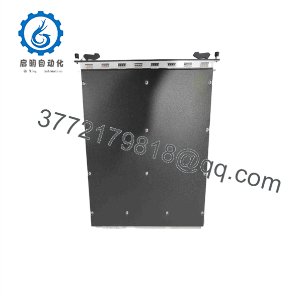
DO3201
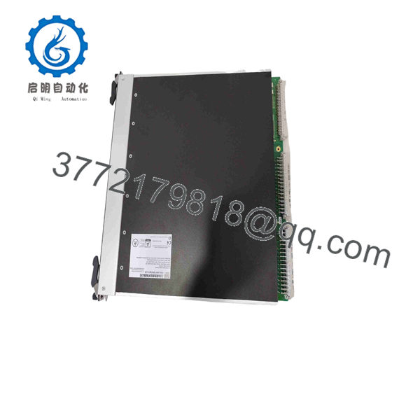
DO3201
Troubleshooting Quick Reference
| Symptom | Possible Cause | Relevance to This Part | Quick Check Method | Recommendation |
|---|---|---|---|---|
| Several shutdown outputs are inactive | Lost 24 V DC field supply, open output common, blown fuse, terminal-board issue, external safety interlock active | ❌ Usually low | Measure approved field voltage at the output terminal board and compare with the field-supply reference. Check upstream fuses, circuit protection, and common-return continuity. | Repair field power and terminal issues before replacing . Group failures usually originate in shared field wiring or supply distribution. |
| One solenoid or interposing relay does not energize | Open coil, damaged cable, failed field fuse, loose terminal, output channel fault, logic not commanding output | ⚠️ Medium | Confirm command state in Tricon diagnostics, then measure voltage at the applicable terminal and directly across the load. Check coil resistance with power isolated. | If the safety application commands the output and field supply is present but no voltage reaches the load, investigate the output channel and terminal board. |
| Output LED indicates ON but field device remains OFF | Open load circuit, blown branch fuse, incorrect field common, failed relay coil, terminal-board wiring fault | ❌ Usually low | Measure output voltage at the module/terminal board and then at the field device. Compare with a working output channel. | Repair the field circuit first. An ON LED alone does not prove that voltage reaches the actuator. |
| Field device energizes when it should be de-energized | Wiring cross-connection, shorted cable, relay welded closed, output channel stuck on, forced logic point | ✅ High | Put the process in an approved safe condition. Review force tables and cause-and-effect logic. Remove the field conductor only under the approved maintenance procedure and observe the output state. | Treat this as a safety-critical fault. Investigate logic, field wiring, relay contacts, and diagnostics immediately. |
| Tricon reports an I/O or module fault | Module not fully seated, terminal-board mismatch, backplane connector issue, failed module, configuration mismatch | ✅ High | Review Tricon diagnostic messages. With the system in the approved maintenance state, inspect latching, connectors, module label, rack slot, and associated termination hardware. | Verify the exact assembly and hardware revision. Do not substitute a different Tricon output module without an approved change process. |
| Output drops out intermittently | Loose terminal, weak field supply, vibration, overheating load, bad relay socket, intermittent cable, output channel fault | ⚠️ Medium | Trend event logs. Measure supply voltage during the event. Inspect terminals and relay sockets during a planned outage. Compare behavior with another channel using a similar load. | Correct external electrical issues first. If the fault follows the output channel after controlled testing, replace the module. |
| All outputs change state after a maintenance event | Wrong terminal connections, lost field common, controller application change, module installed in wrong slot, safety system not restored correctly | ✅ High | Stop and verify the as-built drawings, slot location, terminal numbers, wire markers, and Tricon configuration. Compare pre-maintenance and post-maintenance diagnostics. | Do not continue trial-and-error testing. Restore the validated configuration and execute the approved functional test. |
| Inductive output faults or repeated output failures | Missing flyback diode, incorrect transient suppression, excessive coil current, wrong polarity, field surge | ⚠️ Medium | Inspect each relay, solenoid, and contactor coil for approved suppression. Measure coil current and examine wiring polarity against the loop diagram. | Add or repair suppression only if approved by the SIS design. Do not install a diode where it would slow a required de-energize-to-trip action. |
| Replacement module does not operate | Wrong revision, incompatible terminal board, incorrect slot, unrecognized configuration, damaged backplane connector | ✅ High | Compare complete front and rear labels, terminal-board part number, chassis location, and hardware configuration against the removed component. Record system diagnostics before and after insertion. | Stop installation until engineering confirms compatibility. In a safety system, “close enough” is not a replacement strategy. |
| Output state in Tricon diagnostics differs from physical field state | Wiring issue, terminal board problem, failed load, failed loopback/diagnostic path, output module fault | ✅ High | Compare the logic-solver command, module status, terminal voltage, and field-device feedback. Document each reading at the same moment. | Escalate through the SIS maintenance process. This mismatch can reveal a dangerous failure that requires immediate corrective action. |
❗ Safety warning: Never jumper, force, bypass, or manually hold a output energized to keep production running. A digital output in a Tricon system may control an emergency shutdown valve, trip relay, burner fuel shutoff, fire-and-gas response, or other safety instrumented function. Any bypass requires the site’s approved impairment, management-of-change, and compensating-measures process.
❗ Inductive-load warning: Do not add surge suppression based on habit. A standard flyback diode can extend a solenoid’s drop-out time. In de-energize-to-trip circuits, that delay can be unacceptable. Follow the approved loop design and proof-test record.
If you need support, provide a clear photo of the module label and rear connector, chassis and slot location, terminal-board part number, Tricon diagnostic logs, output command state, measured field voltage, load resistance, and the applicable cause-and-effect or loop drawing.
Frequently Asked Questions
What is the TRICONEX ?
The is identified in aftermarket listings as a Triconex digital output module for Tricon safety-system applications. It is associated with 24 V DC discrete output functions used to operate field devices in safety and critical-control circuits.
Is a communication module or a digital output module?
The available aftermarket listings conflict. Some call it a communication module, while others call it a digital output module. The part prefix “DO” strongly suggests a digital-output function, but that is not enough to establish exact configuration, channel count, or compatibility. Confirm the module’s full label, hardware revision, Tricon chassis documentation, and official Triconex part reference before purchasing or installing it.
How many output channels does have?
Do not rely on publicly available reseller claims. One source describes 16 outputs, while another describes 32 outputs. This conflict is exactly why the physical module label, associated terminal board, and approved Triconex documentation must control the purchase decision.
Does use 24 V DC field power?
Several aftermarket sources identify as a 24 V DC output module. However, you must verify field-supply range, output polarity, channel grouping, maximum current, fuse requirements, and load-suppression design from the exact OEM documentation before connecting field wiring.
Can I replace with another Triconex 24 V DC output module?
No, not without formal engineering approval. Two Triconex modules may both be 24 V DC outputs but differ in chassis compatibility, termination hardware, diagnostics, fault behavior, output polarity, current capacity, firmware expectations, and safety certification scope. Replacement must follow the validated SIS hardware configuration and management-of-change procedure.
Can I hot-swap ?
Do not assume it is hot-swappable. Even where Tricon hardware supports controlled module replacement, output modules connect to live safety circuits and field loads. Follow the exact Triconex maintenance manual, site bypass procedure, cause-and-effect review, and proof-test requirements. An unauthorized live swap can create a trip, loss of protection, or unintended field-device action.
Will replacing the module change the Tricon application program?
The application program normally remains in the Tricon controller, but a module replacement can still cause configuration faults, changed diagnostic behavior, or field-output issues if the hardware revision or termination arrangement differs. Capture diagnostics, verify module identity, and perform the approved post-maintenance functional test before returning the safety function to service.
Why is a New Surplus cheaper than OEM supply?
New Surplus units may originate from unused project spares, plant inventory, system upgrades, distributor stock, or equipment decommissioning. Price alone does not prove authenticity, lifecycle status, or safety suitability. For an SIS part, request exact-unit photos, part and revision confirmation, serial-number traceability where available, packaging photos, a written warranty, and documented handling history.
What test evidence should I request before purchasing a refurbished ?
Request close photos of the exact unit, labels, connectors, latches, and any terminal-board interfaces; visual inspection results; serial-number and revision recording; compatible-rack recognition testing where appropriate; output-channel test evidence using a safe simulated load; diagnostic verification; and a written QC report. A supplier bench test does not replace site commissioning, loop checks, functional testing, and proof testing under the approved safety lifecycle procedure.



