
 WhatsApp: +86 16626708626
 Email:
  Phone: +86 16626708626
Description
Key Technical Specifications
| Parameter | Value |
|---|---|
| Manufacturer | UniOP |
| Model | ETOP306 |
| Product Type | HMI / Operator Panel |
| Series | eTOP Series 300 |
| Display | 5.7-inch TFT color |
| Resolution | 320 × 240 pixels |
| Colors | 64K |
| Backlight | LED |
| Touchscreen | Analog resistive |
| User Memory | 64 MB internal Flash |
| Processor | 32-bit RISC |
| Ethernet | 10/100 Mbps |
| USB | USB host |
| Serial Interfaces | RS-232 / RS-485 / RS-422 |
| Power Supply | 24 V DC, 18–30 V DC |
| Maximum Current | 0.55 A at 24 V DC |
| Operating Temperature | 0 to 50 °C |
| Storage Temperature | −20 to +70 °C |
| Humidity | 5–85% RH, non-condensing |
| Front Protection | IP65 |
| Rear Protection | IP20 |
| Faceplate Dimensions | 187 × 147 mm |
| Panel Cutout | 176 × 136 mm |
| Depth | 45 + 4 mm |
| Weight | Approximately 1.0 kg |
| Software | UniOP Designer 6 |
| Mounting | Panel mount |
The manufacturer documentation identifies the ETOP306 as a 5.7-inch TFT HMI with 320 × 240 resolution, resistive touchscreen, 64 MB user memory, Ethernet, USB, and optional fieldbus modules.
The technical manual specifies 24 V DC operation across an 18–30 V DC range, 0.55 A maximum current at 24 V DC, IP65 front protection, IP20 rear protection, and 0–50 °C operating temperature.
Product Introduction
The UniOP ETOP306 is a compact industrial HMI operator panel from the eTOP Series 300. It uses a 5.7-inch TFT color display, 320 × 240 resolution, analog resistive touch, Ethernet, USB, and serial communication interfaces for machine and building automation applications.
The panel is compatible with UniOP Designer 6 and supports more than 150 communication drivers according to the technical documentation. Optional plug-in modules provide additional fieldbus and network connectivity.
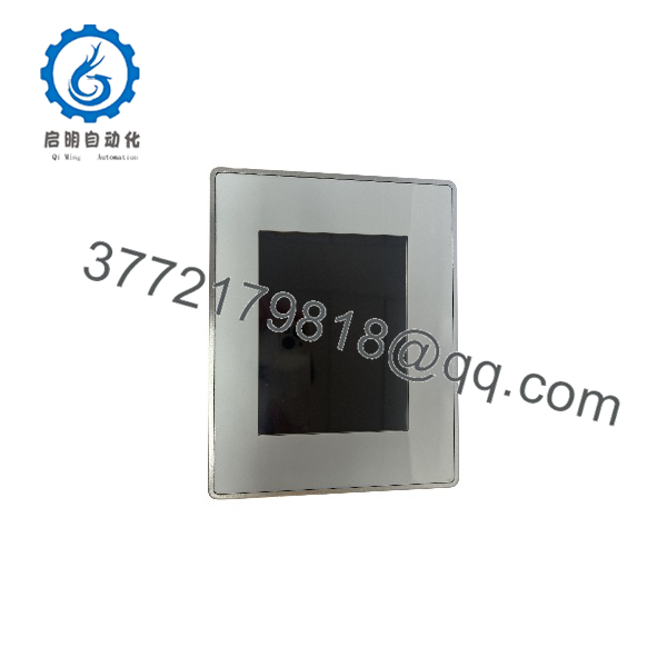
ETOP306
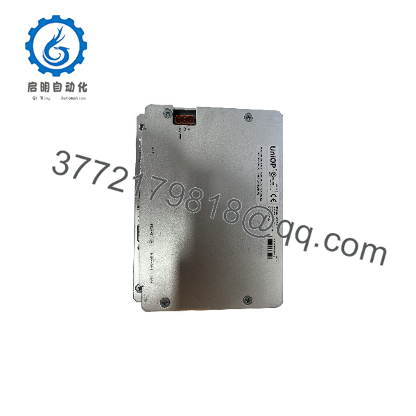
ETOP306
Installation & Configuration Guide
Stage 1: Pre-Installation Preparation — Approximately 10 Minutes
⚠️ Safety First: Place the machine in a safe state and follow the site’s lockout/tagout procedure before disconnecting the HMI power supply.
Tools Required:
- ESD wrist strap
- Screwdriver
- Digital multimeter
- Connector labels
- Smartphone/camera
- Existing HMI project backup
Before removal:
- Record the complete ETOP306 model marking.
- Photograph the rear connectors and wiring.
- Record the Ethernet configuration if Ethernet is being used.
- Back up the HMI application through the existing UniOP programming environment.
- Record communication driver and PLC settings.
- Photograph any optional TCM/SCM communication module installed in the panel.
The ETOP Series 300 supports application transfer and firmware upgrades through Ethernet and USB.
Stage 2: Removing the Old HMI — Approximately 5 Minutes
- Shut down the machine or controlled process according to site procedures.
- Isolate the 24 V DC supply.
- Verify that the HMI power terminals are de-energized.
- Label all communication cables.
- Disconnect Ethernet, USB, serial, and power connections as installed.
- Release the panel mounting hardware.
- Remove the ETOP306 carefully from the panel opening.
⚠️ Keep the old HMI until the replacement has been tested. Its configuration is often more useful than an assumed default configuration.
Stage 3: Installing the New HMI — Approximately 10 Minutes
- Verify that the replacement is an ETOP306.
- Confirm the panel cutout is approximately 176 × 136 mm.
- Inspect the gasket and front-panel sealing surface.
- Insert the HMI into the panel opening.
- Secure the mounting hardware evenly.
- Reconnect the 24 V DC supply.
- Reconnect Ethernet and serial communication cables.
- Reinstall any optional communication module in its original position.
The published mechanical dimensions are approximately 187 × 147 mm for the faceplate and 45 + 4 mm for the depth.
Self-Checklist:
- model confirmed
- 24 V DC supply verified
- Polarity checked
- Panel cutout verified
- Communication cables labeled
- Optional module configuration preserved
- Mounting hardware secured
Stage 4: Power-On & Testing — Approximately 10–15 Minutes
- Check the 24 V DC supply with a multimeter before powering the HMI.
- Energize the HMI.
- Allow the operating/runtime environment to complete startup.
- Confirm touchscreen response.
- Check Ethernet link status.
- Verify communication with the connected PLC/controller.
- Open the HMI application.
- Test representative operator commands.
- Check alarms and historical alarm functions.
- Verify data acquisition and trend displays.
The supports alarms, historical alarm lists, recipes, data acquisition, trends, multilingual applications, and password protection through its UniOP software environment.
Frequently Asked Questions (FAQ)
Q: What is the UniOP ?
The is a 5.7-inch industrial HMI operator panel designed for factory and building automation. It combines a TFT color display, resistive touchscreen, Ethernet, USB, and serial communication interfaces.
Q: What power supply does the require?
The specified input is 24 V DC, with an operating range of 18–30 V DC. Maximum consumption is specified as 0.55 A at 24 V DC.
Q: What software is used to program the ?
The eTOP Series 300 is compatible with UniOP Designer 6. The documentation also states that the platform supports more than 150 communication drivers.
Q: Does have Ethernet?
Yes. The has a 10/100 Ethernet interface. Ethernet can be used for communication with external devices and for HMI programming/data transfer.
Q: What is the display resolution?
The standard specification is 320 × 240 pixels on a 5.7-inch TFT color display. The display uses LED backlighting and an analog resistive touchscreen.
Q: Can I use a different eTOP model as a direct replacement?
Not automatically. The eTOP Series 300 includes different display sizes and mechanical dimensions. The has a 176 × 136 mm panel cutout, so a different model may require mechanical and software changes.
Q: What are the environmental ratings?
The documented operating temperature is 0 to 50 °C, with storage from −20 to +70 °C and 5–85% relative humidity, non-condensing. The front panel is rated IP65, while the rear is IP20.



