
 WhatsApp: +86 16626708626
 Email:
  Phone: +86 16626708626
Description
Key Technical Specifications
| Parameter | TPCM7000 |
|---|---|
| Manufacturer | UNIPOWER |
| Series | PowerCassette TPCM |
| Model | TPCM7000 |
| Function | AC/DC front-end rectifier |
| Input Voltage | 85–264 VAC |
| Output Voltage | 48 VDC |
| Maximum Output Current | 16.7 A |
| Maximum Output Power | 800 W |
| Standby Output | 5 VDC, 0.25 A |
| Power Factor Correction | Yes |
| Input EMI Filter | Class B |
| Hot-Swap | Yes |
| Output ORing | Integrated |
| Current Sharing | Active |
| Rack Compatibility | 1U, 19-inch TPCM rack |
| Dimensions | Approx. 41 × 127 × 254 mm |
| Operating Temperature | 0 to 70 °C |
| Isolation, Input-Output | 3,000 VAC minimum |
| Isolation, Input-Ground | 1,500 VAC minimum |
| Output-Ground | 50 VDC |
| Safety Standards | UL60950, CSA22.2 No. 60950, EN60950 |
The original PowerCassette documentation identifies the TPCM7000 as the 48 VDC / 16.7 A / 800 W member of the standard rear-input/output TPCM family. The TPCM7000E is a separate front-IEC-input version rated at 600 W and 12.5 A, so the suffix matters during replacement.
The module is approximately 1.6 inches high × 5 inches wide × 10 inches deep (41 × 127 × 254 mm) and uses a single hot-swappable connector.
Product Introduction
The UNIPOWER TPCM7000 is a 48 VDC modular rectifier designed for high-power front-end DC systems. It converts universal AC input from 85–264 VAC into a regulated 48 VDC output at up to 16.7 A, providing up to 800 W of DC power.
The TPCM architecture is intended for multi-module rack installations. A compatible 1U, 19-inch shelf can accommodate multiple TPCM modules, while active current sharing and output ORing allow the modules to operate in redundant configurations and support live replacement.
For maintenance teams, the important point is that TPCM7000 is a rack-system component, not simply a standalone 48 V power supply. The shelf, mating connector, airflow direction, and module configuration must be considered when planning a replacement.
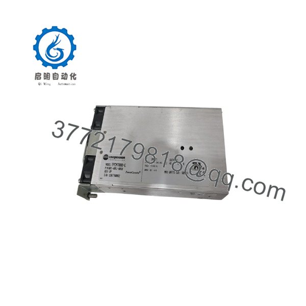
TPCM7000
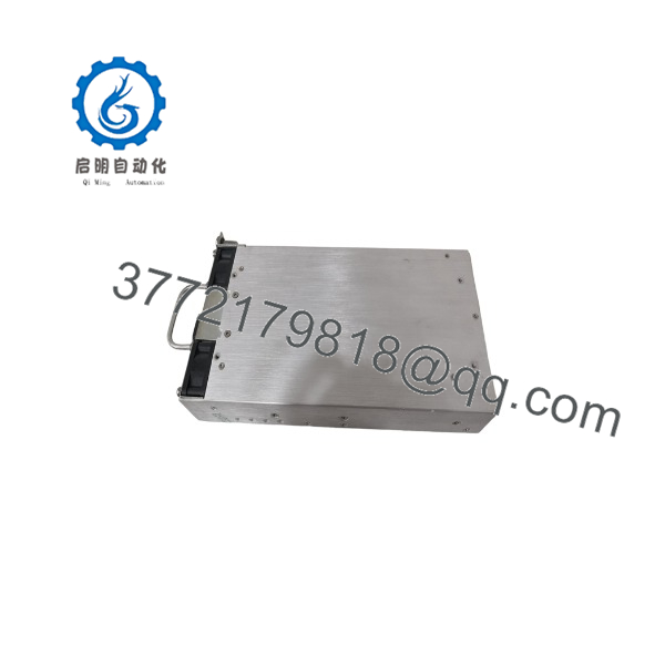
TPCM7000
Installation & Configuration Guide
Stage 1 — Pre-Installation Preparation | ~5 minutes
- Identify the complete module designation: TPCM7000, including any suffix such as
-Ror-Z. - Confirm that the installed shelf is compatible with the TPCM family.
- Record the existing module position and system configuration.
- Check the AC input arrangement and DC output distribution.
- Photograph the front panel, connector area, and shelf wiring.
- Review the site’s electrical safety and LOTO procedure.
⚠️ Do not substitute TPCM7000E for without checking the rack and input arrangement. The E version uses front IEC input and has a different power rating.
Stage 2 — Remove the Existing Module | ~3–5 minutes
The was specifically designed for hot-swappable rack operation.
- Confirm that the system is configured for module replacement under load.
- Verify that the remaining rectifiers can carry the connected load.
- Observe the rack manufacturer’s hot-swap procedure.
- Release the module retaining mechanism.
- Pull the module straight out using the front handle.
- Inspect the rack connector for contamination, discoloration, or mechanical damage.
The TPCM architecture uses staged pin engagement and output ORing, allowing a properly configured module to be removed or inserted without interrupting the DC bus.
Stage 3 — Install the Replacement | ~3–5 minutes
- Verify the replacement model and suffix.
- Inspect the connector and housing.
- Confirm that the airflow direction matches the rack installation.
- Align the module with the rack guides.
- Insert it fully until the connector is seated.
- Secure the front retaining mechanism.
- Confirm that adjacent modules remain correctly seated.
For the standard , the published option -R reverses airflow and requires output derating. Do not install a reverse-airflow variant into a thermal design intended for standard airflow without checking the rack’s cooling arrangement.
Stage 4 — Power-On & Functional Testing | ~10–15 minutes
- Check the module seating and retaining mechanism.
- Observe the AC Power/Fail and DC Power Good indicators.
- Measure the DC bus voltage.
- Confirm that the module begins sharing load with the other rectifiers.
- Check the load current if system monitoring is available.
- Verify that no abnormal fan noise or thermal alarm is present.
- Confirm downstream equipment remains within its normal operating voltage range.
- Record the module serial number and installation position.
The TPCM design includes integral LED status indication, control/monitoring functions, and active current sharing.
Frequently Asked Questions (FAQ)
What is the output of the UNIPOWER ?
The standard provides 48 VDC at up to 16.7 A, corresponding to a maximum output power of 800 W.
What AC input does the accept?
The published specification gives a universal 85–264 VAC input range. The unit incorporates power-factor correction and a Class B EMI input filter.
Is the hot-swappable?
Yes. The TPCM family is designed as a hot-swappable modular architecture. The system uses staged connector engagement and output ORing so a module can be replaced while the remaining modules maintain the DC bus, provided the rack is correctly configured and the load permits the replacement.
Can multiple modules operate together?
Yes. The PowerCassette system supports multiple modules in a 1U rack, with active current sharing and output ORing. This allows the rack to be configured for higher capacity and redundancy.
What is the difference between and TPCM7000E?
The standard is the rear-input/output version rated at 800 W, 48 VDC, 16.7 A. The TPCM7000E uses front IEC input and is rated at 600 W, 48 VDC, 12.5 A. They should therefore not be treated as interchangeable without checking the rack and application.
What does the -R suffix mean?
The -R option indicates reverse airflow, with exhaust directed from the back toward the front. The published documentation specifies output derating for this configuration.
What does the -Z option provide?
The -Z suffix specifies the I²C serial communications option, providing additional control and monitoring capability where supported by the system architecture.
What should I verify before ordering a replacement?
At minimum, confirm:
- Complete model number and suffix
- 48 VDC output requirement
- Required output current
- Standard vs. front-input
Econfiguration - Standard vs. reverse-airflow configuration
- I²C option if installed
- Compatible UNIPOWER rack/shelf
- Connector and mechanical fit
- Existing system load and redundancy configuration
For a legacy TPCM installation, the suffix and rack configuration are just as important as the base model number.



