
 WhatsApp: +86 16626708626
 Email:
  Phone: +86 16626708626
Description
Key Technical Specifications
| Parameter | Specification |
| Channel Count | 8 fully isolated differential inputs |
| Input Signal Range | 4 to 20 mA current loop, 0 to 10 VDC voltage |
| A/D Conversion Resolution | 16-bit successive approximation |
| Isolation Voltage | 500 VAC channel-to-channel and channel-to-backplane |
| Update Time | < 10 ms for all 8 channels |
| Backplane Current Draw | 250 mA @ 5 VDC, 120 mA @ 24 VDC |
| Input Impedance | 250 \Omega for current inputs, > 1 M\Omega for voltage |
| Accuracy Error | \pm 0.05% of full scale at 25 °C |
| Operating Temperature | 0 to +60 °C (32 to 140 °F) |
| Relative Humidity | 5% to 95% non-condensing |
Product Introduction & Supply Chain Strategy
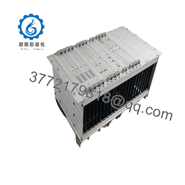
The Valmet 542821-5A is an 8-channel isolated analog input module engineered for the Damatic xD and DNA distributed control systems (DCS). It converts raw field variables—such as pressure, temperature, and flow transmitter outputs—into precise digital values for the central processing unit. Deployed extensively in pulp and paper mills, chemical processing plants, and power generation facilities, this board manages critical regulatory control loops where signal isolation is mandatory to prevent ground loops from corrupting process data.
From a procurement perspective, sourcing the 542821-5A as New Surplus is a calculated risk-mitigation strategy. Because Valmet has transitioned support toward newer control architectures, relying on standard factory lead times during an unexpected card failure invites extreme stock-out costs. Purchasing a verified New Surplus unit establishes a reliable insurance policy on-site. This approach secures original OEM performance and structural longevity without the high asset deterioration risks, degraded capacitors, and short lifespans typical of third-party refurbished hardware.

- 542821-5A
Installation & Configuration Guide
Stage 1: Pre-Installation (Prep & Safety)
- Execute full lock-out/tag-out (LOTO) procedures on the corresponding marshalling cabinet power distribution sub-panel.
- Put on a grounded, static-dissipative wrist strap connected to the cabinet earth ground point to protect CMOS components.
- Photograph the existing module front panel connections, status LEDs, and any side-mounted jumper matrices to preserve the current configuration state.
Stage 2: Removal
- Unplug the terminal block assemblies from the front panel by loosening the retaining screws evenly; do not pull directly on the field wiring harness.
- Disengage the top and bottom chassis lock tabs simultaneously.
- Slide the legacy module straight forward out of the sub-rack guides, ensuring minimal lateral pressure to avoid bending the backplane pins.
Stage 3: Installation (Clone & Seat)
- Verify that the jumper settings on the new 542821-5A exactly mirror the old unit for current/voltage selection per channel.
- Align the board with the sub-rack card guides and slide it smoothly into the slot until the backplane connector mates securely.
- Press the module firmly until the mechanical locking ears snap into place, ensuring a gas-tight seal on the bus line.
Stage 4: Power-On & Testing
- Measure the 24 VDC auxiliary power rail at the terminal strip using a calibrated digital multimeter to confirm voltage stability is within a 20% safety margin.
- Reattach the field wiring terminal blocks and apply system power.
- Observe the startup self-test LED sequence; the green RUN LED must stabilize, and the amber/red ERR LED must remain completely dark. Validate that the DCS controller successfully establishes an I/O communication handshake.
Firmware/Software Versions & Upgrade Notes
The 542821-5A board contains internal programmable logic chips that must match your system’s software release version.
- Target Firmware: This hardware build runs optimized firmware revision V3.4.
- Compatibility Matrix: It maintains full backward compatibility with Damatic xD systems running system software version 5.2 and higher. It is not fully compatible with legacy system versions below V4.0 without a system configuration patch, as older drivers will cause communication timeout errors on the backplane bus.
- Upgrade/Downgrade Warning: Avoid forcing a firmware downgrade on this board to match an ancient system block. Instead, configure the DCS database to recognize the revised hardware ID. Modifying firmware outside an OEM-sanctioned flashing utility can corrupt the onboard EEPROM, permanently bricking the module’s communication stack.
Frequently Asked Questions (FAQ)
Is this Valmet 542821-5A unit brand new, or is it a repaired part?
This module is a genuine Brand New Surplus unit. It has never been installed in an active industrial environment, was not pulled from a decommissioned facility, and has undergone no component-level repairs or soldering. It is original OEM inventory stored in an ESD-safe environment, opened only briefly for our standard inbound quality control inspection.
Why is the pricing higher than refurbished boards found online?
Our pricing reflects the true Total Cost of Ownership (TCO). While refurbished alternatives are cheaper upfront, they carry unquantifiable risks like aged capacitors, stressed relays, and latent thermal damage. Saving a few hundred dollars on procurement can cause tens of thousands of dollars in unplanned downtime. This New Surplus board delivers pristine OEM reliability, giving you a 10-15 year operating life expectancy.
How do you verify that this module works before shipping it?
Every 542821-5A goes through a standardized operational verification process. We confirm inbound traceability through serial number checking, perform physical inspection of backplane connectors, and run functional testing inside a live sub-rack environment. This process includes testing power-on diagnostics, verifying the communication handshake, and running simulated I/O loop tests across all 8 channels to check accuracy.
Can I hot-swap this card while the DCS process loop is live?
Hot-swapping is not recommended for this specific module generation. Removing the card while the backplane is energized can induce transient voltage spikes, which can disrupt adjacent I/O modules on the same bus rack. To prevent unexpected shutdowns or communication dropouts across the node, power down the specific chassis slot or sub-rack before replacement.
Does this analog card retain its configuration if cabinet power drops?
The 542821-5A relies on physical hardware jumper positions for basic channel configuration (such as selecting between 4-20 mA and 0-10 V ranges), which cannot be altered by a power loss. The operational parameters and calibration coefficients are pushed directly from the DCS controller memory during the power-on boot sequence, so no local battery backup is required to retain application logic.


