
 WhatsApp: +86 16626708626
 Email:
  Phone: +86 16626708626
Description
3. Key Technical Specifications
| Parameter | Value |
|---|---|
| Manufacturer | Valmet Automation |
| Model Number | A413071 |
| Product Type | CPU Central Processor Module |
| Installation Method | Rack Mounted |
| Primary Function | Controller Processing and System Management |
| Application | PLC / DCS Automation Systems |
| System Architecture | Legacy Valmet Control Platform |
| Hardware Category | CPU Processor Board |
| Controller Role | Main Execution Processor |
| Availability Status | Obsolete / Surplus Market |
| Service Life Status | Legacy Support Environment |
| Replacement Requirement | Verify firmware and hardware revision compatibility |
4. Product Introduction
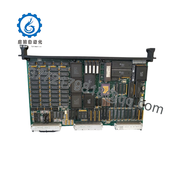
The VALMET A413071 is a CPU Central Processor Module used within legacy Valmet automation systems. As the primary controller processor, it executes application logic, manages communications, and coordinates control functions across the installed PLC or DCS platform. Similar A4130xx-series modules are deployed as the main processing element within Valmet and Metso automation environments.
In operating plants where modernization has been deferred, replacing a failed A413071 can restore system availability without a full control system migration. Engineers should verify firmware revisions, rack compatibility, and configuration backups before installation.

- A413071
5. Installation & Configuration Guide
Stage 1: Pre-Installation Preparation
Estimated Time: 10–15 Minutes
⚠️ Safety First
- Notify operations personnel of the planned outage.
- Confirm process equipment is in a safe state.
- Apply Lock-Out/Tag-Out procedures.
- Remove control power.
- Wait at least 5 minutes for capacitor discharge.
Tools Required
- ESD wrist strap
- PH1 screwdriver
- Fluke 115 multimeter
- Wire identification labels
- Smartphone camera
- Flashlight
Data Backup
- Export all controller programs.
- Backup configuration databases.
- Document:
- IP addresses
- Node addresses
- Communication settings
- Photograph:
- DIP switches
- Jumpers
- Rack location
- Terminal wiring
⚠️ Critical Action
Record the firmware revision before removing the existing CPU.
I’ve seen projects lose nearly 48 hours because the replacement CPU shipped with a newer firmware revision that the existing communication modules would not accept.
Stage 2: Removing the Old Module
Estimated Time: 5–10 Minutes
- Remove front covers and protective panels.
- Label all connectors.
- Disconnect communication cables.
- Release retaining clips.
- Pull the module straight out.
Inspect the Rack
Check for:
- Bent backplane pins
- Oxidation
- Dust accumulation
- Connector damage
⚠️ Important
Keep the removed CPU available until the replacement has completed operational testing.
Stage 3: Installing the New Module
Estimated Time: 10 Minutes
Step 1 – ESD Preparation
- Wear a grounded wrist strap.
- Handle the board only by its edges.
Step 2 – Configuration Clone (CRUCIAL)
- Verify:
- Model number
- Hardware revision
- Board identification
- Replicate:
- DIP switches
- Jumpers
- Node addresses
- Termination settings
❗ This is the most common rookie mistake, but it happens constantly. Take a picture before you pull it. I can’t stress this enough.
Step 3 – Install the CPU
- Align rack guides.
- Insert evenly.
- Press firmly until seated.
- Confirm retaining clips lock.
Step 4 – Reconnect Wiring
- Reinstall communication connectors.
- Verify shield grounding.
- Tighten terminals appropriately.
Self-Checklist
- Model verified
- DIP settings duplicated
- Wiring secure
- CPU seated fully
- Retaining clips locked
Stage 4: Power-On & Testing
Estimated Time: 15–20 Minutes
Pre-Power Checks
- Verify 24 V supply integrity.
- Check for shorts using a multimeter.
- Confirm ground continuity.
Power-Up Procedure
- Energize rack power only.
- Observe startup LEDs.
- Verify normal boot sequence.
- Connect engineering workstation.
- Verify CPU detection.
- Confirm firmware version.
- Restore configuration if required.
- Perform communication testing.
- Conduct I/O verification.
Functional Verification
- CPU diagnostics clear
- Communication links active
- No watchdog faults
- I/O responding correctly
- Process values updating normally
⚠️ Troubleshooting Note
- Solid fault LED → possible firmware mismatch.
- No network communication → verify addressing and communication settings.
- Intermittent faults → inspect rack connectors and backplane condition.
6. Frequently Asked Questions (FAQ)
Q1. Can I hot-swap the VALMET A413071?
No.
CPU modules in legacy Valmet systems are generally not designed for hot replacement. Removing the processor under power can interrupt rack communications and potentially damage the backplane. Shut down control power first.
Q2. Is the A413071 obsolete?
Yes.
The A413071 belongs to an older generation of Valmet automation hardware. Most available inventory today comes from surplus stock, plant shutdown inventories, or specialized automation suppliers. Similar A4130xx-series processor modules are primarily found through the secondary market.
Q3. Is this module available as New Original?
Sometimes.
Legacy Valmet inventory generally falls into three categories:
- Factory Sealed
- New Surplus
- Refurbished (tested)
Always request photographs, serial labels, and test documentation before purchasing.
Q4. Will I lose my control logic if I replace the CPU?
Possibly.
The answer depends on how the original system stores application programs and configuration data.
Before removal:
- Backup all controller files.
- Save communication settings.
- Archive engineering workstation projects.
Never assume the program is stored elsewhere.
Q5. What should I verify before ordering?
Verify:
- A413071 part number
- Hardware revision
- Firmware version
- Rack compatibility
- Backplane type
- Communication architecture
I’ve personally seen engineers order the correct part number but overlook a revision difference that prevented startup.
Q6. Why do supplier prices vary so much?
The largest factors are:
- New Surplus versus Refurbished condition
- Traceability documentation
- Functional testing level
- Warranty coverage
For a production-critical controller, documented testing is usually worth more than the lowest purchase price.
Q7. What quality-control process should a supplier perform?
Inbound Inspection & Traceability
- OEM label verification
- Serial number documentation
- Anti-counterfeit inspection
- Visual checks for:
- Corrosion
- Scratches
- Rework marks
- UV discoloration
Live Functional Testing
- Installation in a compatible Valmet test rack
- Power-on verification
- Communication handshake testing
- CPU diagnostic validation
- Continuous operation for at least 24 hours
- Formal test report generation
Electrical Parameter Testing
- 500 V Megger insulation test (>10 MΩ)
- Ground continuity check
- Hipot testing where applicable
Firmware & Configuration Verification
- Firmware identification
- Hardware revision recording
- DIP switch documentation
- Configuration backup
Final QC & Packaging
- QC inspector sign-off
- ESD-safe packaging
- Bubble-wrap protection
- Heavy-duty corrugated carton
- QC Passed label with inspection date
Test photographs and startup videos should be available upon request.
Common Replacement Pitfalls
❗ Firmware Revision Mismatch
I’ve watched technicians spend two days troubleshooting communication timeouts after installing a replacement CPU with a different firmware revision.
Always document the existing firmware before ordering.
❗ DIP Switch and Jumper Errors
Factory defaults rarely match plant settings.
Photograph everything before removal.
❗ Connector and Wiring Differences
Even closely related Valmet processor revisions may have connector differences.
Never wire from memory.
❗ Power Supply Capacity
Verify rack power consumption and maintain at least a 20% spare capacity margin.
A replacement CPU may have slightly different current requirements.
❗ Electrostatic Discharge (ESD)
I once watched a processor board fail immediately after installation because it was handled without ESD protection during winter maintenance.
Wear a grounded wrist strap and use an ESD-safe work surface.
Keep these checks in mind and you’ll save yourself 90% of typical rework time.


