
 WhatsApp: +86 16626708626
 Email:
  Phone: +86 16626708626
Description
3. Key Technical Specifications
| Parameter | Value |
|---|---|
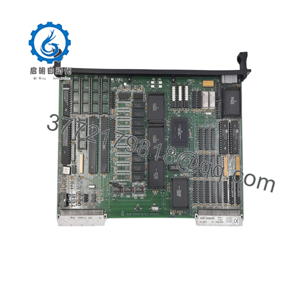
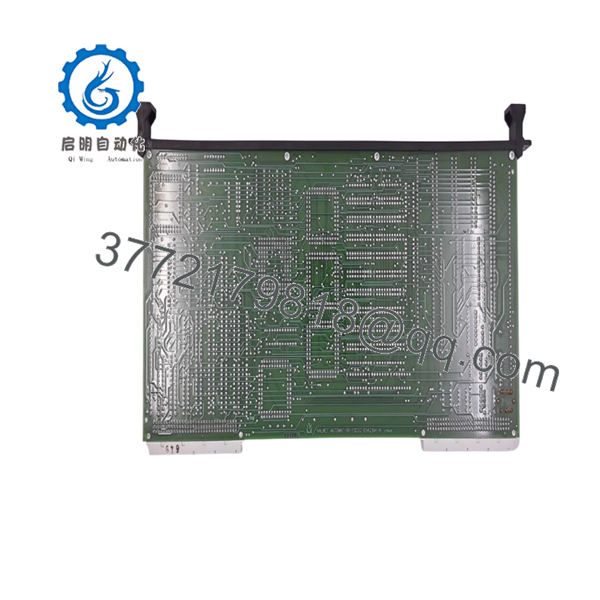
| Manufacturer | Valmet Automation |
| Model Number | A413075 |
| Product Type | FBU Fieldbus Controller Module |
| Known Revisions | Ver.05, Ver.07, Ver.08 |
| Primary Function | Fieldbus Communication Control |
| Installation Method | Rack Mounted |
| Supply Voltage | 24 V DC |
| Operating Temperature | -10 °C to +55 °C |
| Communication Role | Network and Controller Interface |
| System Compatibility | Legacy Valmet / Metso Control Systems |
| Country of Origin | Finland |
| Availability Status | Obsolete / Surplus Market Only |
4. Product Introduction
The VALMET A413075 is an FBU Fieldbus Controller Module used within legacy Valmet automation architectures. Its primary role is managing fieldbus communications between controllers, distributed I/O assemblies, and networked process equipment. Available hardware references identify the module as a Fieldbus Controller used in Valmet and Metso control environments.
In operating pulp and paper mills, power plants, and process facilities still running legacy Valmet systems, the A413075 is commonly sourced to replace failed communication hardware while avoiding a larger control system migration project. Firmware revision and network configuration verification are essential before installation.

- A413075
- A413075
5. Installation & Configuration Guide
Stage 1: Pre-Installation Preparation
Estimated Time: 10–15 Minutes
⚠️ Safety First
- Notify operations personnel of planned downtime.
- Confirm all controlled equipment is in a safe state.
- Apply Lock-Out/Tag-Out procedures.
- Remove control power.
- Wait 5 minutes for capacitor discharge.
Tools Required
- ESD wrist strap
- PH1 screwdriver
- Fluke 115 multimeter
- Wire markers
- Smartphone for documentation
- Flashlight
Data Backup
- Export controller configuration files.
- Record all network addresses.
- Document fieldbus parameters.
- Photograph:
- DIP switches
- Jumper settings
- Connector locations
- Network cabling
- Rack slot assignment
⚠️ Critical Action
Record the existing firmware revision before removing the module.
I’ve seen technicians replace a communication controller only to discover the replacement firmware revision did not match the rest of the network. The resulting communication timeout fault took two days to isolate.
Stage 2: Removing the Old Module
Estimated Time: 5–10 Minutes
- Remove cabinet covers as required.
- Label all communication cables.
- Disconnect fieldbus connectors carefully.
- Release retaining clips.
- Pull the module straight outward.
Inspect the Rack
Verify:
- No bent backplane pins
- No corrosion
- No dust buildup
- No damaged connectors
⚠️ Important
Retain the original module until the replacement has completed startup and communication testing.
Stage 3: Installing the New Module
Estimated Time: 10 Minutes
Step 1 – ESD Preparation
- Wear a grounded wrist strap.
- Handle the board only by the edges.
Step 2 – Configuration Clone (CRUCIAL)
- Verify:
- A413075 part number
- Hardware revision
- Firmware revision
- Replicate:
- DIP switch settings
- Jumpers
- Node addresses
- Bus termination settings
❗ This is the most common rookie mistake, but it happens constantly. Take a picture before you pull it. I can’t stress this enough.
Step 3 – Install Module
- Align the guide rails.
- Insert evenly into the rack.
- Seat the module fully.
- Verify locking clips engage.
Step 4 – Reconnect Wiring
- Reconnect communication cables.
- Verify shield grounding.
- Tighten terminals correctly.
Self-Checklist
- Part number verified
- DIP switches duplicated
- Network wiring connected
- Module fully seated
- Locking clips engaged
Stage 4: Power-On & Testing
Estimated Time: 15–20 Minutes
Pre-Power Checks
- Verify 24 V DC supply.
- Check for shorts using a multimeter.
- Confirm ground continuity.
Power-Up Procedure
- Energize the rack.
- Observe startup LEDs.
- Verify normal boot sequence.
- Connect engineering workstation.
- Confirm module detection.
- Verify firmware revision.
- Test fieldbus communications.
- Verify connected devices appear online.
Functional Verification
- Communication status healthy
- No network alarms
- Field devices online
- Controller communication active
- Diagnostic logs clear
⚠️ Troubleshooting Note
- Solid fault LED → firmware mismatch or hardware failure.
- No communication → verify node address and termination resistor settings.
- Intermittent network faults → inspect cable shielding and grounding.
6. Frequently Asked Questions (FAQ)
Q1. Can I hot-swap the VALMET A413075?
Generally, no.
Most legacy Valmet fieldbus architectures were not designed for live replacement of communication controllers. Removing the module under power can interrupt network traffic and potentially generate backplane faults. Shut down the rack before replacement.
Q2. Is the A413075 a CPU module?
No.
Available documentation identifies the A413075 as an FBU/FBC Fieldbus Controller rather than a CPU processor. Its primary function is communication management between controllers and field devices.
Q3. Is the A413075 obsolete?
Yes.
The module belongs to an older generation of Valmet automation hardware. Most available inventory today comes from surplus stock, decommissioned facilities, or specialized automation suppliers.
Q4. What is the most common replacement problem?
Firmware mismatch.
I’ve personally seen communication modules with the correct hardware number refuse to communicate because the installed network expected an earlier firmware revision.
Always document the original firmware before ordering.
Q5. Why is network communication unavailable after replacement?
The most common causes are:
- Incorrect node address
- Missing termination resistor
- Firmware revision mismatch
- Incorrect baud rate settings
- Damaged fieldbus cabling
Start troubleshooting with the DIP switches and termination settings before assuming the replacement module is faulty.
Q6. Why do prices vary between suppliers?
The biggest factors are:
- New Surplus vs Refurbished condition
- Traceability documentation
- Functional testing level
- Warranty coverage
A tested module with documented communication testing is usually worth the additional cost when compared with an unverified warehouse spare.
Q7. What quality-control process should a supplier perform before shipment?
Inbound Inspection & Traceability
- Verify OEM labels.
- Record serial numbers.
- Perform anti-counterfeit checks.
- Inspect for:
- Corrosion
- Scratches
- Rework marks
- UV yellowing
Live Functional Testing
- Install in a compatible Valmet test rack.
- Verify startup sequence.
- Test fieldbus communications.
- Confirm network handshakes.
- Run continuously for at least 24 hours.
- Generate a formal test report.
Electrical Parameter Testing
- 500 V Megger insulation test (>10 MΩ)
- Ground continuity verification
- Hipot testing where applicable
Firmware & Configuration Verification
- Record firmware revision.
- Record hardware revision.
- Photograph switch settings.
- Backup configuration data if available.
Final QC & Packaging
- Inspector sign-off.
- Anti-static ESD packaging.
- Bubble-wrap protection.
- Heavy-duty corrugated carton.
- QC Passed label with date.
Test photos and communication test videos should be available upon request.
Common Replacement Pitfalls
❗ Firmware Revision Mismatch
I’ve seen fieldbus networks remain offline for two days because a replacement module was running a different firmware revision than the installed controller.
Document the existing version before ordering.
❗ DIP Switch Misconfiguration
Factory defaults rarely match plant requirements.
Take photographs before removal and duplicate every setting.
❗ Fieldbus Termination Errors
Communication networks often require specific termination resistor settings.
One incorrectly configured node can take down an entire segment.
❗ Power Supply Loading
Verify total rack power consumption and maintain at least a 20% power margin.
Legacy power supplies often operate close to capacity.
❗ Electrostatic Discharge (ESD)
I once watched a technician handle a communication board during winter maintenance without an ESD strap. The module failed immediately during startup.
Use a grounded wrist strap and ESD-safe work surface every time.
Keep these checks in mind and you’ll save yourself 90% of typical rework time.


