
 WhatsApp: +86 16626708626
 Email:
  Phone: +86 16626708626
Description
Key Technical Specifications
| Parameter | Specification |
| Module Type | Gate Drive Unit (GDU) Add-On Interface Board |
| Power Supply input | 24 VDC (\pm 10% tolerance) |
| Signal Transmission | High-speed isolated gate drive pulses |
| Channels/Outputs | Multi-channel switching control outputs |
| Isolation Design | Optocoupler or pulse-transformer galvanic isolation |
| Response Propagation Delay | < 1 \mus |
| Physical Weight | 0.71 lbs (0.32 kg) |
| Form Factor | Compact plug-in circuit card assembly |
| Cooling | Passive convection inside protective sub-rack |
| Operating Temperature | 0 to +55 °C (32 to 131 °F) |
Product Introduction & Supply Chain Strategy
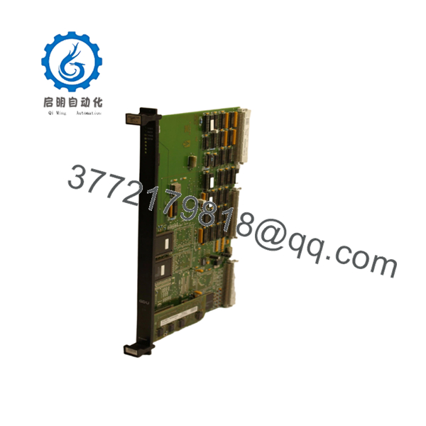
The Valmet A413095 is a specialized Gate Drive Unit (GDU) module designed to function as an add-on board within Metso/Valmet drive automation and distributed control systems. This board serves as the critical hardware link between high-level logic controllers and high-power electronic switching components, ensuring rapid, isolated transmission of firing pulses. Found mostly in heavy-duty paper mill drives, turbine controllers, and large-scale process automation systems, the A413095 manages precise timing signals where any propagation failure directly compromises the safety of the entire power stack.
Because Valmet has officially discontinued this module, maintaining plant reliability requires a transition away from standard just-in-time procurement. Sourcing the A413095 as a New Surplus asset represents a high-ROI strategic insurance policy against catastrophic downtime. Opting for a verified new surplus unit guarantees zero structural aging on sensitive optocouplers or high-speed logic chips, bypassing the severe failure rates, hidden thermal fatigue, and minimal warranty terms that make refurbished boards a high-risk gamble for critical process loops.

- VALMET A413095
Installation & Configuration Guide
Stage 1: Pre-Installation (Prep & Safety)
- Enforce strict lock-out/tag-out (LOTO) protocols on both the 24 VDC control bus and the main high-voltage power inverter bus feed.
- Verify complete discharge of intermediate DC-link capacitors using a calibrated digital multimeter before touching any internal boards.
- Put on an ESD wrist strap connected to a verified panel grounding busbar; document all existing hardware revisions and physical ribbon-cable routing paths.
Stage 2: Removal
- Unplug any auxiliary interface connections or fiber-optic links connected to the top face of the card assembly.
- Back out the retaining screws securing the A413095 board to the main carrier chassis or control rack frame.
- Pull the module straight outward from its alignment pins, ensuring even tension across the interface to prevent physical stress on the motherboard connector pins.
Stage 3: Installation (Clone & Seat)
- Match the hardware revision numbers and physical jumper links on the new A413095 board to mirror the legacy unit exactly.
- Align the board precisely with the guide pins on the primary carrier module or sub-rack assembly slot.
- Seat the module firmly into its socket until the board-to-board connectors are completely bottomed out, then hand-tighten all grounding and retaining screws.
Stage 4: Power-On & Testing
- Apply control voltage power while leaving the main high-voltage power stack isolated to conduct low-voltage logic verification.
- Monitor the integrated diagnostic LEDs on the module; the primary status lights must indicate a stable communication handshake without indicating a gate fault state.
- Execute local system self-tests via the DCS engineering station to verify that the gate driver pulses correspond properly to simulated controller demands before re-energizing the main power circuits.
Firmware/Software Versions & Upgrade Notes
The A413095 is a hardware-driven gate interface card, meaning its function depends primarily on physical component matching rather than downloadable flash applications.
- Hardware Revision Tracking: Always document the board revision level (e.g., Rev 04 vs. Rev 06) silk-screened onto the PCB before completing a swap.
- Compatibility Hazards: A mismatch in hardware revisions can alter the expected gate pulse propagation delays or base drive current limitations. Using an incorrect board revision can trigger immediate overcurrent faults on older power inverter frames.
- Upgrade Risks: Avoid changing firmware on the overarching controller module simultaneously during a hardware card replacement. Isolating the physical board swap from software adjustments minimizes troubleshooting confusion and prevents configuration loop timeouts on the backplane.
Frequently Asked Questions (FAQ)
What defines this Valmet A413095 module as “New Surplus”?
This A413095 unit is a genuine New Surplus module sourced directly from verified industrial overstock channels. It has never spent time inside an operating drive panel, was not recovered from a decommissioned manufacturing plant, and contains zero component-level re-soldering. It remains in its original non-conductive packaging until final quality verification testing.
Why shouldn’t we buy a significantly cheaper refurbished A413095 board?
Refurbished gate drive units frequently fail under heavy thermal load because standard cosmetic cleanings cannot fix internal crystal degradation inside optocouplers or substrate fatigue in aging transistors. Purchasing a refurbished board to save a small portion of your procurement budget introduces a weak point that can cause unexpected reactor or line shutdowns, resulting in massive downtime losses. This New Surplus board provides the original 10-15 year factory lifecycle.
Does this GDU module come with a performance guarantee?
Yes, this unit includes a comprehensive 2-year warranty coverage plan that fully replaces any defunct factory terms. Each card undergoes comprehensive physical and functional inspection, including power-on diagnostics, bus interface verification, and static isolation testing before it leaves our facility.
Does the A413095 require on-site software programming before startup?
No programming is required directly on the A413095 board itself. It acts as an execution component for drive switching logic. You must ensure that physical jumpers match the legacy unit’s positions so the card routes control signals correctly according to your main controller’s configuration.
How should we store this card to prevent shelf degradation?
Keep the A413095 sealed inside its moisture-resistant, static-shielding enclosure within a climate-controlled space at temperatures between 15 and 30 °C (59 to 86 °F). Maintaining low relative humidity protects the delicate circuit connections from oxidized film build-up, ensuring the module remains ready for immediate emergency installation during an unplanned outage.


