
 WhatsApp: +86 16626708626
 Email:
  Phone: +86 16626708626
Description
Key Technical Specifications
| Parameter | Specification |
|---|---|
| Manufacturer | Metso Automation / Valmet / Neles |
| Part Number | A413139 (AOU-4 / AOU4) |
| Module Type | 4-Channel Analog Output Module |
| Output Ranges | 0 to 20 mA, 4 to 20 mA, or 0 to 10 VDC |
| Channel Count | 4 Configurable Analog Output Channels |
| Resolution & Precision | 12-bit / 16-bit D/A Conversion |
| Galvanic Isolation | Channel-to-channel and channel-to-backplane isolation |
| System Compatibility | Metso / Valmet Industrial Automation Backplanes (DNA / Damatic / maxDNA) |
| Operating Temperature | 0 to +60 °C (Standard Industrial) |
| Weight | Approx. 0.45 kg (0.99 lbs) |
Product Introduction & Supply Chain Strategy
The Metso/Valmet A413139 (AOU-4) is a 4-channel analog output module engineered for critical control loops across paper mills, power generation, and chemical process facilities. Working as the primary interface between the central controller and field final-control elements, the A413139 delivers high-precision current loops (4–20 mA) to control valves, variable frequency drives (VFDs), and electro-pneumatic positioners.
From a supply chain continuity standpoint, keeping an A413139 module in safety stock is essential. Unlike input cards that merely monitor parameters, an output module failure causes loss of actuator control, holding a control valve frozen or forcing a fail-safe shutdown. Refurbished output cards often suffer from aged digital-to-analog converters (DACs), drifted voltage references, and degraded output transistors that introduce loop jitter or output clamping. Purchasing New Surplus guarantees factory-calibrated DAC linearity, full galvanic isolation, and zero-downtime protection against lead-time delays.
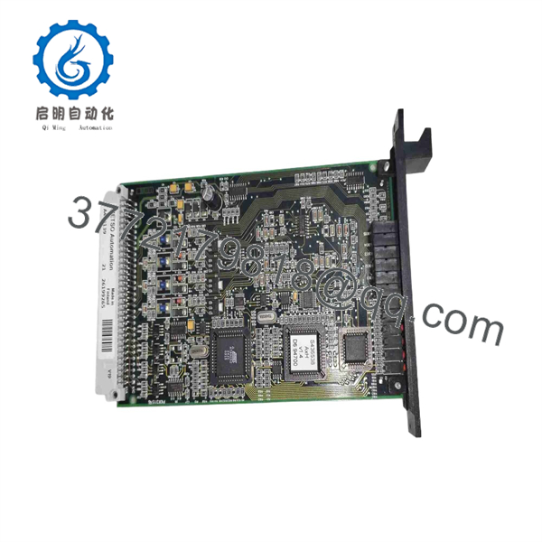
A413139
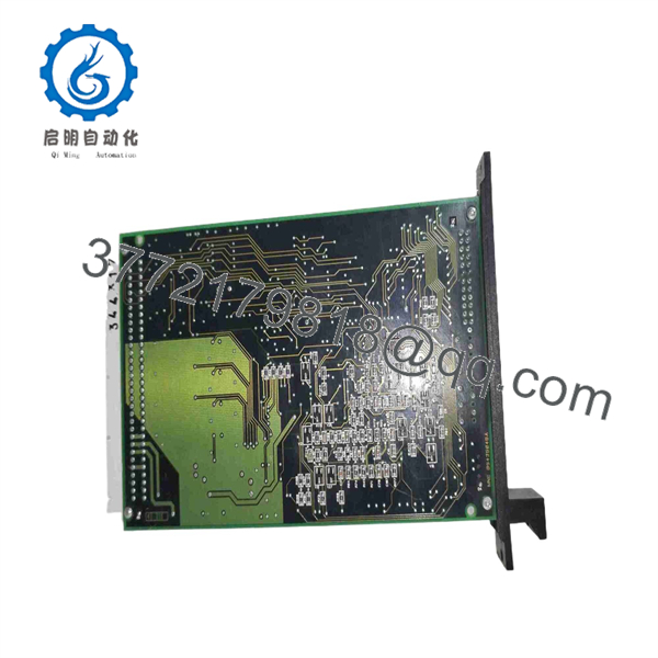
A413139
Installation & Configuration Guide
1
Stage 1: Pre-Installation (Safety & Loop Prep)
Notify control operators, isolate loops, and put on ESD wrist strap
1.Stage 1: Pre-Installation (Safety & Loop Prep):Notify control operators, isolate loops, and put on ESD wrist strap.
Notify system operators to switch target control loops (valves, VFDs, positioners) to Manual mode or hardwired bypass before removing the module. Fully de-energize the target rack slot or card cage following standard Lock-Out/Tag-Out (LOTO) protocols. Wear a grounded ESD wrist strap before handling the circuit board. Record existing field terminal wiring and module DIP/jumper settings.
2
Stage 2: Module Removal
Unfasten faceplate screws and remove card from slot
2.Stage 2: Module Removal:Unfasten faceplate screws and remove card from slot.
Unscrew the captive retention screws on the card faceplate. Gently disengage the card’s edge connector from the backplane and slide the module straight out along its guide tracks. Immediately place the removed card into an antistatic shielding bag.
3
Stage 3: Physical Installation
Check hardware options and align card into backplane
3.Stage 3: Physical Installation:Check hardware options and align card into backplane.
Verify that output range jumpers (0–20 mA vs 4–20 mA vs 0–10 V) on the new A413139 match the replaced unit. Align the card edges with the guide rails in the rack slot and push the module inward smoothly until the rear DIN connector fully locks into the backplane. Tighten the faceplate screws.
4
Stage 4: Power-On & Stroke Verification
Apply rack power, check status indicators, and verify loop outputs
4.Stage 4: Power-On & Stroke Verification:Apply rack power, check status indicators, and verify loop outputs.
Re-energize the rack and observe the status LEDs to verify proper boot initialization. Access the engineering software to perform a 0%, 50%, and 100% signal output check, verifying live current loop readings at the field valve or positioner before returning loops to Auto mode.
Configuration & Operational Notes
- Software Channel Mapping: Output mode selection (current vs. voltage mode, failure fallback values, and scaling) is set via the Metso/Valmet automation engineering suite software.
- Fall-back States: Ensure fallback values (e.g., Hold Last Value, Go to 0 mA, or Go to 4 mA) are configured in the software prior to placing the loop into service to guarantee safe machinery behavior during controller loss.
- Power De-energization: Always de-energize the slot or lock out output loops before removing the card to prevent voltage/current spikes that could trigger connected final control elements.
Frequently Asked Questions (FAQ)
Q: What is the main difference between the A413125 and the ?
A: The A413125 (AIU-8) is an 8-channel Analog Input unit used to collect sensor data. The (AOU-4) is a 4-channel Analog Output unit used to send 4–20 mA / 0–10 V signals to drive valves, drives, and positioners.
Q: Can individual channels on the be set to different output ranges?
A: Yes, each channel can be independently configured via system software (and onboard hardware option jumpers where applicable) for 0–20 mA, 4–20 mA, or 0–10 VDC output operation.
Q: Why choose New Surplus over a refurbished output card?
A: Analog output cards directly control physical equipment. Refurbished cards with worn DACs or aged capacitors can experience output signal drift, leading to inaccurate valve positioning or unexpected process trips. New Surplus guarantees factory output accuracy and full component lifespan.
Q: What warranty comes with this module?
A: Every New Surplus Metso Valmet card is shipped in antistatic packaging with verifiable serial numbers and is backed by a full 1-year replacement warranty.



