
 WhatsApp: +86 16626708626
 Email:
  Phone: +86 16626708626
Description
3. Key Technical Specifications
| Parameter | Value |
|---|---|
| Manufacturer | Valmet Automation |
| Model Number | A413383 |
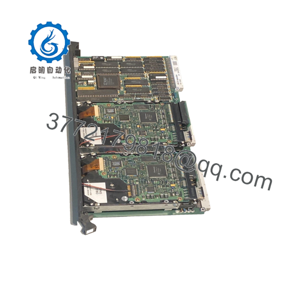
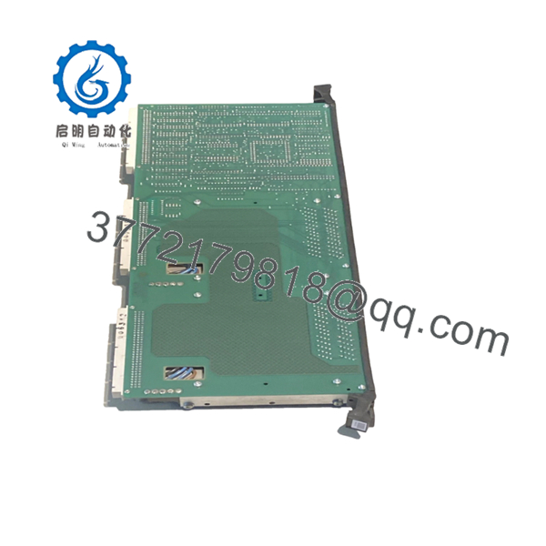
| Product Type | PC Board Module |
| Hardware Category | Industrial Control PCB |
| Installation Method | Rack Mounted |
| Application | PLC / DCS Automation Systems |
| System Role | Control System Board Assembly |
| Platform Generation | Legacy Valmet Automation Platform |
| Availability Status | Obsolete / Surplus Market |
| Typical Condition | New Surplus or Refurbished |
| Warranty Availability | Typically 12 Months from Supplier |
| Replacement Requirement | Verify hardware revision compatibility |
4. Product Introduction
The VALMET A413383 is a PC Board Module used within legacy Valmet automation systems. Available market references identify the module as a control system circuit board intended for installation within existing Valmet control architectures.
In facilities operating older Valmet or Metso automation platforms, the A413383 is typically purchased as a direct replacement spare to maintain system availability. Because OEM technical documentation is limited, engineers should verify board revision, connector configuration, and firmware information before installation.

- A413383
- A413383
5. Installation & Configuration Guide
Stage 1: Pre-Installation Preparation
Estimated Time: 10–15 Minutes
⚠️ Safety First
- Notify operations of the planned maintenance window.
- Confirm the process is in a safe operating condition.
- Apply Lock-Out/Tag-Out procedures.
- Remove all control power sources.
- Wait at least 5 minutes for capacitor discharge.
Tools Required
- ESD wrist strap
- PH1 screwdriver
- Fluke 115 multimeter
- Wire labels
- Smartphone for documentation
- Flashlight
Data Backup
- Export controller configuration files.
- Backup application programs.
- Record all communication settings.
- Photograph:
- Board location
- Rack slot assignment
- DIP switches
- Jumper positions
- Cable connections
⚠️ Critical
Before removing the original board, document all visible revision markings and firmware labels.
I’ve seen maintenance teams install the correct part number only to discover a hardware revision difference that caused communication faults after startup.
Stage 2: Removing the Old Module
Estimated Time: 5–10 Minutes
- Open the control cabinet.
- Remove protective covers.
- Label every connector before disconnection.
- Disconnect cables carefully.
- Release retaining clips or locking mechanisms.
- Pull the board straight out.
Backplane Inspection
Check for:
- Bent connector pins
- Corrosion
- Dust contamination
- Connector wear
⚠️ Important
Retain the original module until the replacement has completed commissioning and operational testing.
Stage 3: Installing the New Module
Estimated Time: 10 Minutes
Step 1 – ESD Protection
- Connect a grounded wrist strap.
- Handle the PCB only by the edges.
Step 2 – Configuration Clone (CRUCIAL)
- Verify:
- A413383 model number
- Hardware revision
- Board markings
- Duplicate:
- DIP switch positions
- Jumper settings
- Address settings
- Termination settings where applicable
❗ This is the most common rookie mistake, but it happens constantly. Take a picture before you pull it. I can’t stress this enough.
Step 3 – Install the Board
- Align the board with rack guides.
- Insert evenly.
- Seat fully into the connector.
- Confirm retaining hardware locks correctly.
Step 4 – Reconnect Wiring
- Reconnect all cables.
- Verify shielding connections.
- Confirm connector engagement.
Self-Checklist
- Correct model number
- Revision verified
- DIP switches match
- Wiring secure
- Board fully seated
Stage 4: Power-On & Testing
Estimated Time: 15–20 Minutes
Pre-Power Checks
- Verify 24 V DC supply integrity.
- Check for shorts using a multimeter.
- Confirm ground continuity.
Power-Up Procedure
- Energize the rack.
- Observe status indicators.
- Verify normal startup sequence.
- Connect engineering workstation.
- Verify module recognition.
- Check communication status.
- Restore configuration if required.
- Conduct I/O verification.
Functional Verification
- No active diagnostics
- Stable communications
- No watchdog alarms
- Correct I/O operation
- Normal process updates
⚠️ Troubleshooting Note
- Fault indication after startup → verify hardware revision and firmware compatibility.
- Communication failure → verify addressing and cable connections.
- Intermittent operation → inspect backplane connectors and grounding.
6. Frequently Asked Questions (FAQ)
Q1. Can I hot-swap the VALMET A413383?
No.
Unless the specific Valmet rack documentation explicitly supports hot replacement, treat the A413383 as a non-hot-swappable module. Removing it under power can create backplane communication faults and potentially damage the hardware.
Q2. Is the A413383 obsolete?
Yes.
The A413383 is generally available only through surplus inventory and legacy automation suppliers. Current market listings identify it as a replacement part for older Valmet control systems.
Q3. Is this a CPU module?
Not necessarily.
Unlike A413001, A413082, and other documented CPU modules, publicly available references identify the A413383 primarily as a PC Board Module. Available documentation does not clearly classify it as the main processor. Verify the exact board function from the installed system documentation before ordering.
Q4. What should I verify before ordering?
Verify:
- A413383 part number
- Hardware revision
- Board markings
- Connector layout
- Rack compatibility
- Existing firmware labels
For legacy Valmet hardware, the revision often matters as much as the part number.
Q5. What is the most common replacement mistake?
DIP switch and jumper settings.
I’ve watched technicians spend hours troubleshooting a replacement board that was functioning perfectly. The only issue was a node address left at factory default.
Photograph everything before removal.
Q6. Why do supplier prices vary significantly?
Several factors affect pricing:
- New Surplus versus Refurbished condition
- Traceability documentation
- Functional testing performed
- Warranty coverage
- Available inventory levels
For obsolete control hardware, documented testing is usually worth paying for.
Q7. What quality-control process should be performed before shipment?
Inbound Inspection & Traceability
- OEM label verification
- Serial number recording
- Anti-counterfeit inspection
- Visual examination for:
- Corrosion
- Scratches
- Rework marks
- UV yellowing
Live Functional Testing
- Installation in a compatible Valmet test rack
- Power-on verification
- Communication testing
- I/O simulation where applicable
- Continuous operation for at least 24 hours
- Formal test report generation
Electrical Parameter Testing
- 500 V Megger insulation resistance test (>10 MΩ)
- Ground continuity verification
- Hipot testing when applicable
Firmware & Configuration Verification
- Record firmware labels
- Record hardware revisions
- Photograph jumper settings
- Document switch configurations
Final QC & Packaging
- Inspector sign-off
- Anti-static ESD packaging
- Bubble-wrap protection
- Heavy-duty corrugated carton
- QC Passed label with inspection date
Test photos and startup videos should be available upon request.
Common Replacement Pitfalls
❗ Firmware Revision Mismatch
I’ve seen communication faults persist for two days because the replacement board carried a different firmware revision than the original system.
Document the existing revision before ordering.
❗ DIP Switch Misconfiguration
Factory defaults rarely match the plant configuration.
Take photographs before removal and duplicate every setting.
❗ Connector Assumptions
Never assume connector assignments are identical between revisions.
Always compare physical hardware and documentation.
❗ Power Supply Capacity
Verify rack power consumption and maintain at least a 20% reserve margin.
Legacy power supplies often have little spare capacity.
❗ Electrostatic Discharge (ESD)
I once watched an engineer handle a legacy PCB during a winter shutdown without an ESD strap. The board failed immediately after power-up.
Use a grounded wrist strap and ESD-safe work surface every time.
Keep these checks in mind and you’ll save yourself 90% of typical rework time.


