
 WhatsApp: +86 16626708626
 Email:
  Phone: +86 16626708626
Description
Key Technical Specifications
| Parameter | A413600 Specification |
|---|---|
| Manufacturer | Metso Automation / Valmet |
| Part Number | A413600 |
| Product Type | Cabinet fan unit |
| Application | PLC chassis/rack cooling |
| Number of fans | 3 |
| Fan voltage | 24 VDC |
| Fan technology | Brushless DC |
| Assembly type | Rack/cabinet fan assembly |
| Approximate weight | 1.10 kg |
| Associated listing | A413600-03 / TK3271-8 |
| Approximate assembly dimensions | 17 × 9 × 5.5 in on one aftermarket listing |
| Manufacturer status | Discontinued |
| Replacement market | New old stock, used, refurbished |
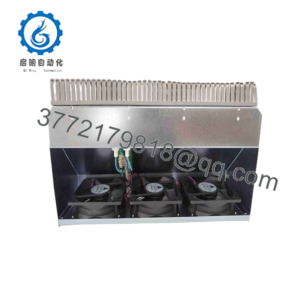
The strongest available part-specific source identifies A413600 as a Metso Automation/Valmet cabinet fan unit containing three 24 VDC brushless fans. Radwell also lists the part as discontinued and gives a weight of approximately 1.10 kg.
A separate Valmet/Metso listing identifies A413600-03 as a fan assembly for a PLC module rack and describes it as containing three 24 V fans. It gives approximate assembly dimensions of 17 × 9 × 5.5 inches. Because those dimensions are shipping/listing measurements rather than an OEM mechanical drawing, they should not be treated as controlled installation dimensions.
Product Introduction
The Metso Automation A413600 is a cabinet cooling assembly designed to maintain airflow around legacy Valmet/Metso PLC hardware. It contains three 24 VDC brushless fans and is identified in aftermarket documentation as a cabinet fan unit or PLC chassis-rack fan assembly.
This is a relatively simple component, but it is important from a reliability standpoint: loss of forced airflow can increase the temperature of PLC cards, power supplies, and other rack electronics. The should therefore be evaluated as a cooling-system component, not as a control or I/O module. The manufacturer has discontinued the part, so maintenance teams supporting legacy Valmet systems should verify fan condition and spare availability before a failed assembly causes an overheating event.
A413600
Installation & Configuration Guide
Stage 1 — Pre-Installation Preparation
Before replacing :
- Place the associated PLC/control system in the approved maintenance condition.
- Follow the plant LOTO procedure.
- Allow at least 5 minutes for stored electrical energy to discharge, unless the site procedure specifies a longer period.
- Identify the fan assembly and record its part number.
- Photograph the existing fan orientation and airflow direction.
- Record the fan power wiring and connector arrangement.
- Check whether the assembly is fitted to a rack, cabinet door, chassis, or dedicated mounting frame.
- Verify that the replacement contains the same number of fans and uses the same 24 VDC supply.
The most important pre-installation check is airflow direction. Installing a physically compatible fan assembly in the wrong orientation can reduce rather than improve cabinet cooling.
Stage 2 — Removing the Existing Fan Assembly
- Confirm that the cabinet is de-energized.
- Isolate the fan supply.
- Remove the cabinet or rack access panel as required.
- Disconnect the fan power connector.
- Label the connector if the wiring is not keyed.
- Remove the fan assembly retaining screws or mounting hardware.
- Withdraw the assembly carefully.
- Inspect the surrounding area for:
- Dust accumulation
- Blocked ventilation paths
- Fan bearing debris
- Overheated wiring
- Damaged connectors
- Loose mounting hardware
- Clean the air path before installing the replacement.
Do not replace only the fan assembly while leaving a heavily contaminated cabinet filter or blocked air inlet in place. Restricted airflow can produce the same symptoms as an undersized or failing fan.
Stage 3 — Installing the Replacement
- Verify that the replacement is .
- Confirm that the assembly contains three 24 VDC brushless fans.
- Compare fan orientation with the original.
- Check the airflow arrows marked on the individual fans, where provided.
- Position the assembly in the original mounting location.
- Secure the mounting hardware evenly.
- Reconnect the 24 VDC supply.
- Verify polarity before energizing.
- Confirm that cables are clear of the fan blades.
- Ensure that cabinet ventilation openings are unobstructed.
No software configuration is normally associated with the fan assembly itself. The critical configuration points are electrical polarity, supply voltage, mounting position, and airflow direction.
Stage 4 — Power-On & Testing
After installation:
- Verify the fan supply voltage before startup.
- Energize the fan assembly.
- Confirm that all three fans start.
- Check for abnormal bearing noise or vibration.
- Verify airflow direction.
- Confirm that no fan intermittently stops.
- Check cabinet/rack temperature after the system reaches normal operating conditions.
- Inspect the fan wiring for excessive heating.
- Confirm that any cabinet temperature alarm clears normally.
A simple “all three fans spin” test is useful but incomplete. For a production cabinet, the acceptance check should also verify airflow, cabinet temperature, abnormal vibration/noise, and any existing cabinet thermal alarm.
Frequently Asked Questions (FAQ)
1. What is Metso ?
is a Metso Automation / Valmet cabinet fan unit used for cooling automation equipment. The part is specified with three 24 VDC brushless fans.
2. Is a PLC control module?
No. is a cooling fan assembly, not a CPU, I/O module, communications card, or power-control board. It supports the thermal management of the PLC cabinet/rack.
3. How many fans are included?
The part-specific documentation identifies three 24 VDC brushless fans in the assembly.
4. What voltage do the fans use?
The available part-specific documentation identifies the fans as 24 VDC.
5. Is still manufactured?
Available industrial parts databases identify the as discontinued by the manufacturer. Existing inventory, new old stock, used assemblies, refurbished units, and repair options are therefore more relevant procurement channels than normal OEM distribution.
6. Can I replace with three generic 24 V fans?
Not automatically. The replacement must match the physical mounting arrangement, airflow direction, airflow capacity, electrical current, connector/wiring, fan dimensions, and cabinet cooling requirements. A generic fan with the same nominal voltage is not necessarily an equivalent thermal replacement.
7. What should I check when buying a replacement ?
Verify:
- Exact part number
- Three-fan configuration
- 24 VDC fan voltage
- Fan condition
- Connector and wiring arrangement
- Airflow direction
- Physical mounting dimensions
- Fan rotation/noise
- Evidence of functional testing
- Condition and warranty
For a used assembly, ask the supplier to verify all three fans independently, rather than assuming that a visually clean assembly has three functional fans.



