
 WhatsApp: +86 16626708626
 Email:
  Phone: +86 16626708626
Description
3. Key Technical Specifications
| Parameter | Value |
|---|---|
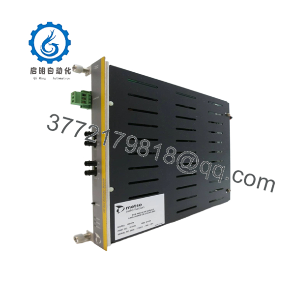
| Manufacturer | Valmet Automation / Metso Automation |
| Model Number | IOP341 |
| Product Type | Positioner Module |
| Hardware Category | I/O Processing / Position Control Module |
| Installation Method | Rack Mounted |
| Power Method | Loop Powered |
| Indicators | Status LEDs |
| Connector Type | Card-Side Connector |
| Application | DCS / Process Control Systems |
| Typical Use | Position and Motion Signal Processing |
| Lifecycle Status | Obsolete |
| Availability | New Surplus / Refurbished Market |
4. Product Introduction
The VALMET IOP341 is a Positioner Module used in legacy Valmet and Metso distributed control systems. Available references identify the module as a rack-mounted I/O processing and position-control interface that handles position feedback, motion-related signals, and process control communications within DCS architectures.
In field deployments of older Valmet automation systems, modules such as the IOP341 are commonly retained long after the original OEM production lifecycle ends. When failures occur, plants typically replace the module with verified surplus inventory rather than undertake an immediate DCS migration. Firmware compatibility, addressing configuration, and connector verification should be completed before installation.

- IOP341
5. Installation & Configuration Guide
Stage 1: Pre-Installation Preparation
Estimated Time: 10–15 Minutes
⚠️ Safety First
- Notify operations of planned downtime.
- Verify the process is in a safe state.
- Apply Lock-Out/Tag-Out procedures.
- Remove control power.
- Wait at least 5 minutes for capacitor discharge.
Tools Required
- ESD wrist strap
- PH1 screwdriver
- Fluke 115 multimeter
- Wire labels
- Smartphone for documentation
- Flashlight
Data Backup
- Export controller configuration files.
- Record communication parameters.
- Document node addresses.
- Photograph:
- Module location
- DIP switch positions
- Jumper settings
- Terminal wiring
- Communication connectors
⚠️ Critical
Document all module labels and firmware markings before removal.
I’ve seen projects spend two days chasing communication faults because the replacement module had the correct model number but a different firmware revision.
Stage 2: Removing the Old Module
Estimated Time: 5–10 Minutes
- Open the cabinet.
- Remove protective covers.
- Label all connected cables.
- Disconnect field wiring carefully.
- Release locking clips.
- Pull the module straight out.
Backplane Inspection
Inspect for:
- Bent connector pins
- Corrosion
- Dust contamination
- Loose backplane connectors
⚠️ Important
Keep the original IOP341 until the replacement has completed startup and process testing.
Stage 3: Installing the New Module
Estimated Time: 10 Minutes
Step 1 – ESD Protection
- Wear a grounded wrist strap.
- Work on an ESD-safe surface.
- Handle the board only by its edges.
Step 2 – Configuration Clone (CRUCIAL)
- Verify:
- IOP341 model number
- Hardware revision
- Firmware revision
- Duplicate:
- DIP switch settings
- Jumper positions
- Address settings
- Termination settings
❗ This is the most common rookie mistake, but it happens constantly. Take a picture before you pull it. I can’t stress this enough.
Step 3 – Install Module
- Align rack guides.
- Insert evenly.
- Seat fully into the backplane connector.
- Confirm retaining clips lock securely.
Step 4 – Reconnect Wiring
- Reconnect cables according to documentation.
- Verify shield grounding.
- Confirm connector engagement.
Self-Checklist
- Model number verified
- Firmware verified
- DIP settings match
- Wiring secure
- Module fully seated
- Retaining clips engaged
Stage 4: Power-On & Testing
Estimated Time: 15–20 Minutes
Pre-Power Checks
- Verify supply voltage integrity.
- Check for shorts using a multimeter.
- Confirm ground continuity.
Power-Up Procedure
- Energize the rack only.
- Observe status LEDs.
- Verify normal startup behavior.
- Connect engineering workstation.
- Confirm module recognition.
- Verify communication status.
- Restore configuration if required.
- Conduct loop and position-feedback testing.
Functional Verification
- Status LEDs normal
- Communication active
- No diagnostic alarms
- Position feedback responding correctly
- Stable process values
⚠️ Troubleshooting Note
- Solid fault LED → firmware mismatch or hardware failure.
- No communication → verify node addressing and network configuration.
- Unstable position feedback → inspect signal wiring, grounding, and encoder connections.
6. Frequently Asked Questions (FAQ)
Q1. What exactly is the VALMET IOP341?
Based on multiple legacy automation references, the IOP341 is primarily identified as a Positioner Module used within Valmet and Metso DCS environments. Some suppliers also classify it as an I/O processing or distributed control module depending on the application.
Q2. Can I hot-swap the IOP341?
No.
Unless your specific DCS architecture explicitly supports online replacement, treat the IOP341 as a non-hot-swappable module. Removing it under power can generate communication faults and potentially damage the rack interface.
Q3. Is the IOP341 obsolete?
Yes.
Current availability is largely limited to surplus inventory and refurbished automation suppliers. Multiple vendors list the module as discontinued or available only through legacy inventory channels.
Q4. What should I verify before ordering?
Verify:
- IOP341 model number
- Hardware revision
- Firmware revision
- Rack compatibility
- Connector configuration
- Existing system architecture
With legacy Valmet hardware, revision compatibility is often just as important as the base part number.
Q5. What is the most common startup issue after replacement?
Firmware revision mismatch.
I’ve personally seen a replacement communication module initialize correctly but fail communication handshakes because the firmware generation differed from the installed control network.
Always record the original firmware version before ordering.
Q6. Why are some IOP341 units sold as Refurbished?
Because OEM production has ended.
Many available units have been removed from operating plants, tested, repaired where necessary, and returned to service inventory. A properly tested refurbished module can often be a better option than an unverified warehouse spare.
Q7. What quality-control process should be performed before shipment?
Inbound Inspection & Traceability
- OEM label verification
- Serial number recording
- Anti-counterfeit inspection
- Visual inspection for:
- Corrosion
- Scratches
- Rework marks
- UV yellowing
Live Functional Testing
- Installation in a compatible Valmet rack
- Power-on verification
- Communication handshake testing
- Position signal simulation
- Continuous operation for at least 24 hours
- Test report generation
Electrical Parameter Testing
- 500 V Megger insulation test (>10 MΩ)
- Ground continuity verification
- Hipot testing where applicable
Firmware & Configuration Verification
- Firmware version recording
- Hardware revision documentation
- DIP switch photography
- Jumper setting documentation
Final QC & Packaging
- QC inspector sign-off
- Anti-static ESD packaging
- Bubble-wrap protection
- Heavy-duty corrugated carton
- QC Passed label with inspection date
Test photos and startup videos should be available upon request.
Common Replacement Pitfalls
❗ Firmware Revision Mismatch
I’ve seen a technician replace an IOP-series module and spend two days troubleshooting communication timeouts before discovering a firmware revision difference.
Document the original version before ordering.
❗ DIP Switch Misconfiguration
Factory defaults rarely match the plant configuration.
Take photographs before removal and duplicate every switch position.
❗ Connector Assumptions
Never assume identical wiring between revisions.
Always compare drawings and physical hardware.
❗ Power Supply Capacity
Verify rack power loading and maintain at least a 20% reserve margin.
Aging power supplies often become the hidden cause of intermittent faults.
❗ Electrostatic Discharge (ESD)
I once watched an engineer unpack a replacement module during a dry winter shutdown without an ESD strap. The board failed immediately after startup.
Use a grounded wrist strap and ESD-safe work surface every time.
Keep these checks in mind and you’ll save yourself 90% of typical rework time.


