
 WhatsApp: +86 16626708626
 Email:
  Phone: +86 16626708626
Description
3. Key Technical Specifications
| Parameter | Value |
|---|---|
| Manufacturer | Valmet Automation |
| Model Number | M2512201 |
| Product Type | Control Board Module |
| Hardware Category | Industrial Control PCB |
| Installation Method | Rack / Chassis Mounted |
| System Function | Control and Signal Processing |
| Application | DCS / PLC Automation Systems |
| Platform | Legacy Valmet Control Systems |
| Board Construction | Multi-Layer Industrial PCB |
| Lifecycle Status | Obsolete |
| Availability | New Surplus / Refurbished |
| Compatibility Requirement | Verify Hardware Revision Before Installation |
4. Product Introduction
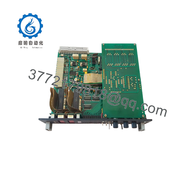
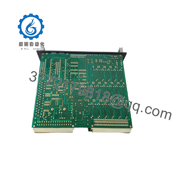
The VALMET M2512201 is a control board module used in legacy Valmet automation architectures. The board performs control, communication, and signal-processing functions as part of the overall DCS or PLC platform installed in process industries such as pulp and paper, power generation, and industrial manufacturing.
In field deployments where legacy Valmet systems remain operational, replacement boards such as the M2512201 are commonly sourced through surplus inventories to maintain plant availability. Before installation, engineers should verify hardware revision levels, firmware versions, and connector compatibility to avoid commissioning delays.

- M2512201
- M2512201
5. Installation & Configuration Guide
Stage 1: Pre-Installation Preparation
Estimated Time: 10–15 Minutes
⚠️ Safety First
- Notify operations of planned downtime.
- Place the process in a safe operating state.
- Apply Lock-Out/Tag-Out procedures.
- Remove all control power.
- Wait at least 5 minutes for capacitor discharge.
Tools Required
- ESD wrist strap
- PH1 screwdriver
- Fluke 115 multimeter
- Wire labels
- Smartphone camera
- Flashlight
Data Backup
- Export controller logic and configuration files.
- Record network settings and node addresses.
- Save current diagnostic information.
- Photograph:
- Rack location
- Wiring layout
- Connector assignments
- DIP switches
- Jumpers
- Board identification labels
⚠️ Critical
Document all firmware and hardware revision labels before removing the existing board.
I’ve seen technicians install the correct board number but the wrong firmware generation. The board powered up normally, yet communications remained offline until a compatible revision was located.
Stage 2: Removing the Old Module
Estimated Time: 5–10 Minutes
- Open the cabinet.
- Remove protective covers.
- Label all cables and connectors.
- Disconnect field and communication wiring carefully.
- Release retaining clips or mounting hardware.
- Pull the board straight out.
Backplane Inspection
Inspect for:
- Bent pins
- Corrosion
- Connector wear
- Dust accumulation
- Oxidation
⚠️ Important
Keep the original module available until the replacement has successfully completed commissioning and process verification.
Stage 3: Installing the New Module
Estimated Time: 10 Minutes
Step 1 – ESD Protection
- Wear a grounded wrist strap.
- Use an ESD-safe work surface.
- Handle the board only by its edges.
Step 2 – Configuration Clone (CRUCIAL)
- Verify:
- M2512201 part number
- Hardware revision
- Firmware labels
- Board assembly markings
- Replicate:
- DIP switch settings
- Jumper positions
- Address settings
- Termination settings
❗ This is the most common rookie mistake, but it happens constantly. Take a picture before you pull it. I can’t stress this enough.
Step 3 – Install Module
- Align guide rails carefully.
- Insert the board evenly.
- Seat fully into the backplane connector.
- Verify locking hardware is engaged.
Step 4 – Reconnect Wiring
- Reconnect all cables.
- Verify shield grounding.
- Confirm connector orientation.
- Inspect terminal tightness.
Self-Checklist
- Part number verified
- Hardware revision verified
- Firmware checked
- DIP switches duplicated
- Wiring secure
- Module fully seated
Stage 4: Power-On & Testing
Estimated Time: 15–20 Minutes
Pre-Power Check
- Verify control supply voltage.
- Check for shorts using a multimeter.
- Confirm ground continuity.
Power-Up Procedure
- Energize the rack only.
- Observe startup LEDs.
- Verify normal initialization.
- Connect the engineering workstation.
- Confirm module recognition.
- Verify firmware information.
- Restore configuration if required.
- Verify communications.
- Conduct I/O and functional testing.
Functional Verification
- No active diagnostics
- Stable communication links
- No watchdog faults
- Correct I/O response
- Normal process operation
⚠️ Troubleshooting Note
- Solid fault LED → suspect firmware incompatibility or hardware revision mismatch.
- No communication → verify addressing and network configuration.
- Intermittent faults → inspect grounding and backplane connectors.
6. Frequently Asked Questions (FAQ)
Q1. Is the VALMET M2512201 still manufactured?
No.
The M2512201 belongs to a legacy generation of Valmet automation hardware. Current availability is generally limited to surplus inventory, warehouse stock, and specialized industrial automation suppliers.
Q2. Can I hot-swap the M2512201?
No.
Unless your specific Valmet platform documentation explicitly supports online replacement, power down the rack before removing the board.
Removing control modules under power can damage connectors and generate communication faults throughout the system.
Q3. What should I verify before purchasing?
Verify:
- Complete M2512201 part number
- Hardware revision
- Firmware EPROM labels
- Connector layout
- Rack compatibility
- Existing controller generation
For legacy Valmet hardware, matching the part number alone is rarely sufficient.
Q4. Will replacing the board erase my control logic?
Possibly.
Depending on the platform architecture, logic and configuration may reside in controller memory, removable storage, EPROM devices, or engineering backups.
Always perform a complete backup before removing any control module.
Q5. What is the most common replacement issue?
Firmware revision mismatch.
I’ve seen replacement boards initialize correctly but fail communications because the firmware generation was newer than the rest of the installed system.
Always document firmware labels before placing an order.
Q6. Why are tested refurbished units often preferred over untested surplus inventory?
Because functionality matters more than appearance.
A refurbished module that has passed communication testing, power-up diagnostics, and load testing generally presents less operational risk than an unverified warehouse spare that has been sitting on a shelf for years.
Q7. What quality-control process should be completed before shipment?
Inbound Inspection & Traceability
- Verify OEM labels.
- Record serial numbers.
- Perform anti-counterfeit checks.
- Inspect for:
- Corrosion
- Scratches
- Rework marks
- UV yellowing
Live Functional Testing
- Install in a compatible Valmet test rack.
- Verify power-up sequence.
- Test communications.
- Simulate I/O where applicable.
- Perform continuous operation for more than 24 hours.
- Generate a formal test report.
Electrical Parameter Testing
- 500 V Megger insulation resistance test (>10 MΩ)
- Ground continuity verification
- Hipot testing where applicable
Firmware & Configuration Verification
- Record firmware versions.
- Record hardware revisions.
- Photograph DIP switches.
- Document jumper settings.
Final QC & Packaging
- QC inspector sign-off.
- Anti-static ESD packaging.
- Bubble-wrap protection.
- Heavy-duty corrugated carton.
- QC Passed label with inspection date.
Test reports, photos, and startup videos should be available upon request.
Common Replacement Pitfalls
❗ Firmware Revision Mismatch
I’ve seen a technician spend an entire weekend troubleshooting communication failures that were ultimately caused by a firmware revision difference.
Record firmware information before ordering.
❗ DIP Switch Misconfiguration
Factory default settings rarely match plant requirements.
Photograph every switch and jumper before removal.
❗ Terminal and Connector Differences
Never assume connector assignments remain unchanged between revisions.
Always compare physical hardware and drawings.
❗ Power Supply Capacity
Calculate rack power consumption and maintain at least a 20% reserve margin.
An overloaded power supply often looks like a defective control board.
❗ Electrostatic Discharge (ESD)
I once watched an engineer handle a replacement board during a dry winter outage without a wrist strap. The module failed immediately after startup.
Use a grounded wrist strap and ESD-safe work surface every time.
Keep these checks in mind and you’ll save yourself 90% of typical rework time.


