WhatsApp: +86 16626708626
 Email:
 Phone: +86 16626708626
Description
Core Product Summary (Brand / Model / Key Attributes)
The Meggitt Vibro-Meter IOC4T (ordering part numbers 200-560-000-111 for card assembly and 200-560-101-017 for specific hardware revision options) is a rear-panel Input/Output (I/O) expansion card designed for the VM600 machinery protection and condition monitoring platform. Functioning as the companion rear card to the MPC4 machinery protection card within VM600 ABE16x 19-inch racks, the IOC4T manages external signal wiring, analog signal routing, and transducer power distribution for critical rotating machinery monitoring.
The IOC4T card provides physical terminal connections for four dynamic sensor input channels (supporting piezoelectric accelerometers, proximity probes, and velocity sensors) and two or four tachometer/speed channels. It features analog output processing, providing raw dynamic signals via front/rear panel connectors and conditioned DC outputs (0/4–20 mA or 0–10 V) proportional to measured vibration parameters. The board also includes discrete relay outputs, keyway signal processing, and direct backplane interconnection with the MPC4 processing card.
Key Technical Specifications
| Parameter | Specification |
| Product Type | Rear Input/Output (I/O) Card for VM600 Machinery Protection System |
| Manufacturer | Meggitt / Vibro-Meter |
| Model Name | IOC4T |
| Card Ordering Numbers | 200-560-000-111 / 200-560-101-017 |
| Compatible Companion Card | MPC4 Machinery Protection Card (Front Slot) |
| Compatible Rack Types | VM600 ABE160 and ABE166 19″ Rack Systems |
| Dynamic Sensor Channels | 4 Channels (Supports Accelerometers, Proximity Transducers, Velocity Sensors) |
| Tachometer / Speed Channels | 2 or 4 Tachometer Input Channels (Phase Reference / Speed Measurement) |
| Raw Analog Outputs | 4 raw voltage outputs (1 per dynamic channel, 0–±10 V range) |
| Conditioned DC Current Outputs | 4 channels: 4 to 20 mA or 0 to 20 mA (Configurable via software/jumpers) |
| Transducer Power Supply | Integrated power distribution outputs for active sensors and proximity transmitters |
| Relay Outputs | Onboard discrete output relays (Configurable for alarm and danger states) |
| Terminal Connection Type | Screw terminal strip blocks or multi-pin connector headers |
| Physical Slot Requirements | Standard 6U Rear Slot (Positioned directly behind the corresponding MPC4 card) |
Detailed Product Overview
The Vibro-Meter IOC4T (part numbers 200-560-000-111 and 200-560-101-017) plays a key role in the VM600 modular machinery protection system architecture. Operating as the signal interface card mounted in the rear of the rack cabinet, it pairs directly with the MPC4 processing card installed in the front slot. This modular separation allows field wiring (sensor cables, analog outputs, and relay lines) to connect permanently at the rear panel without disturbing the front-side processing modules during maintenance.
The IOC4T conditions and routes up to four dynamic vibration signals alongside dedicated speed/phase-reference signals from tachometer sensors. The module delivers transducer power to field sensors, such as eddy-current proximity probe systems and voltage-output accelerometers. In addition to powering sensors, the IOC4T handles signal distribution, outputting unconditioned raw voltage signals for diagnostics while concurrently driving 4–20 mA analog loops to plant Distributed Control Systems (DCS) or Programmable Logic Controllers (PLCs).
Safety interlocks and machine protection alarms are routed through the IOC4T’s discrete relay contacts. Working in conjunction with the front-mounted MPC4 card’s signal processing engine, the IOC4T facilitates hardware trip signals for machine shutdown under excessive vibration or overspeed conditions.
Engineering Selection Highlights
- Matched Card Pair Architecture: Specifically paired with the MPC4 protection card to isolate heavy field wiring to the rear of the VM600 rack while maintaining high-speed digital backplane communication.
- 4-Channel Dynamic & Speed Capability: Manages four independent vibration sensor inputs and auxiliary tachometer channels within a single slot footprint.
- Dual-Output Signal Processing: Delivers simultaneous raw AC voltage signals for spectrum analyzers alongside 4–20 mA DC current signals for DCS automation integration.
- Integrated Transducer Powering: Provides built-in power supply outputs to eliminate external power conditioning requirements for connected proximity probes and sensors.
- Hardwired Alarm Relays: Houses hardware relay logic for local machine shutdown and warning indications under hardware-configured threshold triggers.
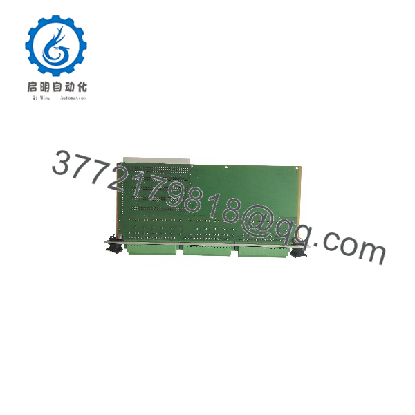
vmf-IOC4T 200560-101-017 200-560-000-111
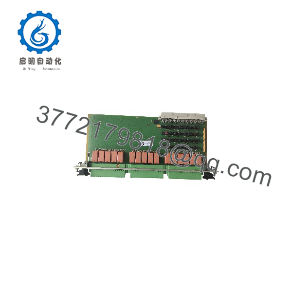
vmf-IOC4T 200560-101-017 200-560-000-111
System Compatibility & Integration Requirements
| Item / Dependency | Verified Compatibility or Requirement | Practical Note |
| Compatible Processing Module | Vibro-Meter MPC4 Machinery Protection Card | Installed directly in the matching front-panel slot opposite the IOC4T. |
| Rack System Chassis | VM600 ABE160 / ABE166 6U 19-inch Racks | Plugs into the rear card cage area of the VM600 chassis. |
| Field Transducers | Proximity Probes, Accelerometers, Velocity Transducers | Requires proper jumper selection or software configuration for sensor power levels. |
| Configuration Software | Vibro-Meter VM600 MPS / MPSX Software | System configuration, relay logic, and output scaling are managed via the host MPC4 module settings. |
Dimensions, Mounting & Connection Notes
- Module Dimensions: Standard 6U height rear slot expansion card.
- Rack Mounting Position: Installed into the rear card cage of VM600 19-inch racks, directly aligned with the front MPC4 processing card.
- Wiring Interface Options: Equipped with removable screw terminal strip blocks or high-density connectors depending on exact hardware revision options (such as 200-560-101-017).
- Terminal Wiring Guidelines: Shielded twisted-pair cables are recommended for dynamic sensor inputs to prevent electromagnetic interference from surrounding high-voltage industrial equipment.
FAQ
What is the Vibro-Meter IOC4T (200-560-000-111 / 200-560-101-017)?
The IOC4T is a rear Input/Output card for the Meggitt Vibro-Meter VM600 machinery protection system. It handles field wiring, sensor power distribution, and output signal conditioning for its paired MPC4 front card.
Which front-panel module does the IOC4T pair with?
The IOC4T is designed to pair directly with the MPC4 machinery protection card in VM600 rack configurations.
How many sensor input channels does the IOC4T support?
The module supports up to four dynamic vibration sensor input channels (accelerometers, proximity probes, velocity sensors) plus dedicated tachometer/speed input channels.
What signal output types does the IOC4T provide?
It provides raw AC voltage outputs for external diagnostic instrumentation, 4–20 mA (or 0–20 mA) DC analog outputs for DCS/PLC integration, and discrete relay contact outputs for alarm/trip actions.
Does the IOC4T provide power to connected field transducers?
Yes, the card includes integrated transducer power outputs to power active sensors such as eddy-current proximity transmitter systems.
Verification & Troubleshooting Notes
- Missing Signal Readings on MPC4 Module: Verify that the rear IOC4T card is fully seated and securely fastened in the rear slot alignment guide. Inspect backplane connectors for pin alignment.
- Transducer Power Output Faults: If proximity probes fail to power up, verify hardware jumper positions or software configurations on the paired MPC4 card, ensuring transducer supply voltage parameters are configured correctly.
- 4–20 mA Current Loop Failures: Check loop impedance on output terminals. Ensure the receiving PLC/DCS input card impedance matches the load capability specified for the IOC4T analog output channels.