
 WhatsApp: +86 16626708626
 Email:
  Phone: +86 16626708626
Description
Key Technical Specifications
| Parameter | Value |
|---|---|
| Manufacturer | Vibro-Meter, formerly associated with Meggitt; now within Baker Hughes Bently Nevada product support history |
| Model Number | CMC16 |
| Ordering Number Format | 200-530-SSS-HHh |
| Product Series | VM600 Condition Monitoring System |
| Product Type | Condition Monitoring Card / intelligent front-end data acquisition unit |
| Card Architecture | VMEbus, 6U format |
| Dynamic Input Channels | 16 individually configurable channels |
| Anti-Aliasing Filters | 16 programmable tracked anti-aliasing filters |
| A/D Conversion | One 14-bit ADC per channel |
| Tachometer / Phase Inputs | Up to 4 among the first 4 channels |
| Tachometer Input Range | 1–24 V pulse; AC-coupled within −24 to +24 V range |
| Tachometer Frequency Range | 0.25 Hz to 10,000 Hz |
| Maximum Pulses Per Revolution | 128 for speed calculation; 1 for phase reference |
| Machine-Speed Resolution | ±1 rpm |
| Process-Value Inputs | Last 12 channels configurable for process values |
| Maximum Input Voltage | 50 V for vibration/process inputs; 3 V for thermocouple inputs |
| Signal Types | Acceleration, velocity, displacement, dynamic pressure, air-gap, rotor/pole profile, speed, phase, dynamic, quasi-static, and process signals |
| FFT Resolution | Up to 3,200 lines |
| Frequency Bands | 10 configurable bands per channel |
| Alarm Capacity | 6 configurable alarms per band with hysteresis deadbands |
| Synchronous Sampling | Order tracking from 1.56 to 400 orders |
| Asynchronous Sampling | Frequency spans from 0–100 Hz through 0–20 kHz |
| Data Collection Modes | Scheduled, on-alarm, on-exception, and oscilloscope-mode capture |
| Transient Trend Buffer | 3,276 values per channel |
| Historic Trend Buffer | 26,200 values per CMC16 |
| Run-Up / Run-Down Storage | 100 spectra of 400 lines per channel |
| Microcontroller | Zilog Z8S180 |
| DSP | Motorola 56002 |
| VME Communication | D16/A24 slave mode; 1 MB/s transfer rate to CPU M |
| Serial Communications | RS-485 multidrop |
| RS-485 Maximum Distance | 1,220 m / 4,000 ft without repeaters |
| RS-485 Data Rate | 19,200 or 38,400 baud, asynchronous |
| RS-485 Isolation | 50 V |
| Power Supply | 5 V DC ±5% |
| Power Consumption | 15 W from 5 V DC supply |
| Operating Temperature | −25 to +65 °C |
| Storage Temperature | −40 to +85 °C |
| Operating Humidity | 0–90% RH, non-condensing |
| Physical Size | 6U × 20 mm × 187 mm; 262 × 20 × 187 mm |
| Weight | Approximately 0.35 kg / 0.77 lb |
| Replacement Requirement | Match the full 200-530 firmware suffix, hardware version, VM600 rack, CPU M configuration, IOC16T input modules, sensor types, and CMS software version |
The CMC16 is the central data-acquisition and analysis card in the Vibro-Meter VM600 Condition Monitoring System. It provides 16 configurable channels, tracked anti-alias filtering, one 14-bit ADC per channel, FFT processing, programmable alarm bands, onboard buffers, and VME/RS-485 communications.
Product Introduction
Vibro-Meter CMC16 is a 16-channel VM600 condition-monitoring card for rotating machinery. It acquires vibration, speed, phase, dynamic-pressure, air-gap, rotor-profile, and process signals, then processes spectra, trends, alarms, and transient data for machinery diagnostics and asset monitoring.
The CMC16 works with a VM600 rack, CPU M module, VM600 CMS software, and compatible IOC16T input modules. It is not a standalone vibration transmitter or a generic PLC card. Match the complete 200-530-SSS-HHh ordering code because the SSS firmware designation and HHh hardware version determine replacement compatibility.
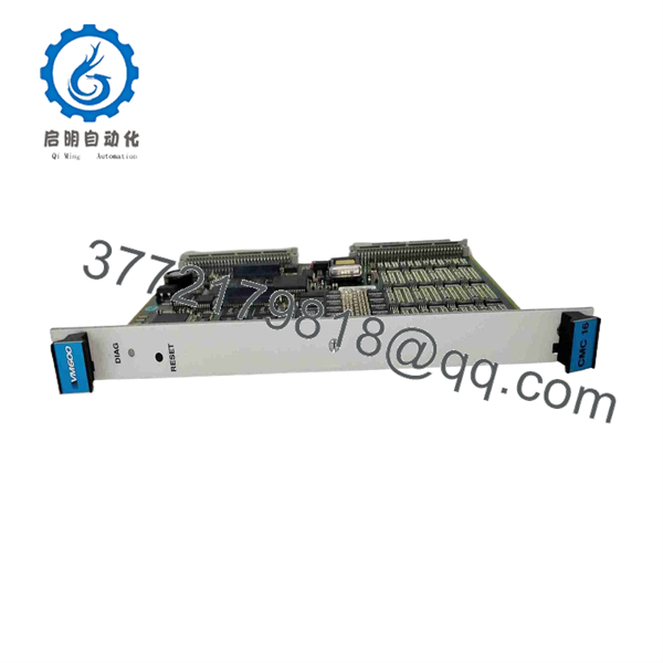
CMC16
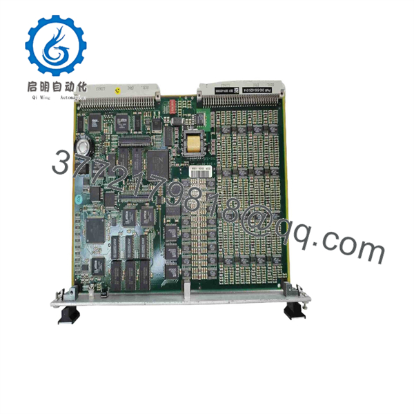
CMC16
Troubleshooting Quick Reference
| Symptom | Possible Cause | Relevance to This Part | Quick Check Method | Recommendation |
|---|---|---|---|---|
| CMC16 is not detected by the rack | Card not seated, missing 5 V DC rack supply, CPU M communication issue, bent backplane contact, failed | ✅ High | Check rack diagnostics; verify 5 V DC at the rack backplane under load; power down under approved procedure and inspect card contacts | Confirm rack power, CPU M status, and card seating before replacing . |
| Front-panel LED shows fault or abnormal status | Internal initialization fault, communication fault, firmware mismatch, failed processor, rack issue | ✅ High | Record the three-color LED state, CMS messages, CPU M diagnostics, and card slot number; compare with a known-good card if available | Preserve diagnostic evidence before swapping. Confirm firmware and hardware version compatibility. |
| All 16 channels show invalid, flatline, or missing data | IOC16T problem, lost rack communication, common sensor supply issue, configuration mismatch, fault | ✅ Medium | Verify whether other cards communicate; inspect IOC16T modules; check common sensor supplies and cable shields; review channel assignments in CMS software | Do not replace until common power, input-module, and software issues are eliminated. |
| One vibration channel reads zero | Open sensor cable, failed accelerometer/proximity transducer, loose IOC16T terminal, wrong channel configuration | ✅ Medium | Check sensor power and continuity at the IOC16T; compare sensor output with a portable analyzer; move the sensor input to a known-good channel only under approved procedures | Field sensor and wiring faults are more common than an individual input failure. |
| Vibration values are unstable or noisy | Poor shield termination, ground loop, damaged cable, loose connector, EMI, sensor mounting problem | ✅ Medium | Inspect cable shields and bonding; compare waveform and spectrum with a portable analyzer; check for 50/60 Hz or VFD switching-frequency components | Correct shielding, grounding, and sensor mounting before replacing the card. |
| Speed or phase reference is missing | Tachometer supply/wiring fault, incorrect trigger edge, weak pulse amplitude, wrong configuration, failed input channel | ✅ Medium | Measure tach pulse at the designated input; confirm pulse level is within the 1–24 V range and frequency is within 0.25–10,000 Hz | Verify tach wiring, pulse polarity, and configuration before replacing . |
| FFT or spectrum data does not update | CMS software connection issue, CPU M communication fault, acquisition schedule disabled, storage full, configuration error | ✅ Medium | Confirm CPU M Ethernet/serial status, review acquisition schedules, check event logs and buffer status, and verify the card appears online | Correct CMS and CPU M communications before replacing the condition-monitoring card. |
| False alarms occur during startup or coast-down | Incorrect alarm bands, inadequate hysteresis, wrong speed reference, unsuitable order tracking setup, process transient | ❌ Low | Review alarm configuration, tach reference, speed profile, and cascade data; compare with startup baseline records | Adjust alarm strategy only under approved machinery-engineering review. Do not remove protection based on nuisance alarms. |
| Replacement communicates but trends differ | Firmware revision mismatch, channel calibration/configuration not restored, incorrect mapping, altered sensor scaling | ✅ High | Compare old and new ordering codes, firmware, hardware version, channel configuration, alarm bands, units, calibration, and rack slot | Restore the verified configuration and validate against baseline data before releasing the system. |
| Card runs hot or repeatedly resets | Rack 5 V supply instability, blocked airflow, overloaded supply, internal card fault, high cabinet temperature | ✅ High | Measure rack 5 V DC supply while the system runs; inspect airflow and rack temperature; compare power draw against 15 W per card | Correct power and thermal issues first. Replace if resets follow the card in a known-good slot. |
❗ Firmware warning: The full ordering format is 200-530-SSS-HHh. The SSS portion identifies embedded software and HHh identifies hardware version. A physically identical can boot but behave differently if firmware does not match the CPU M, CMS software, installed hardware, or existing project configuration. Record the entire label before ordering.
❗ Input-mapping warning: The first four channels can serve as tachometer or phase-reference inputs, while the last 12 can be configured for process values. Do not move sensor cables or copy channel settings blindly. A misplaced tach signal can corrupt order tracking across an entire machine train.
❗ Protection-versus-monitoring warning: The is a condition-monitoring card. It should not be confused with a Machinery Protection Card such as MPC4. Never bypass trip logic, shutdown relays, or machine-protection functions based on a diagnostic issue without approval from the machinery-protection engineer.
❗ Tachometer warning: The tach input accepts 1–24 V pulses over 0.25–10,000 Hz. A marginal pulse, bad shield, wrong trigger edge, or missing phase reference can produce misleading speed, order, and spectrum data. Verify the tach signal at the input before calling the defective.
❗ Backplane warning: Do not force the card into the rack. Bent VME connector contacts can damage the card and the rack backplane. With power removed, inspect the card guides, slot alignment, connector condition, and retention hardware before insertion.
❗ ESD warning: Wear a grounded wrist strap and handle the by its front panel and board edges. I have seen a technician pull a healthy monitoring card, set it on an unprotected cardboard box, and create an intermittent channel fault before the spare ever went back into service.
Keep these checks in mind and you will save yourself 90% of typical rework time. If you need technical support, provide full photos of the 200-530-SSS-HHh label, rack slot, front LED, CPU M diagnostics, CMS error logs, terminal wiring, sensor list, tach waveform, and configuration backup.
Frequently Asked Questions
What is the Vibro-Meter ?
Vibro-Meter is a Condition Monitoring System card used to acquire and analyze machinery-condition data from rotating equipment. It accepts vibration, speed, phase, dynamic, and process signals, performs filtering and FFT analysis, calculates trends and alarm values, and sends results to CMS software through the CPU M architecture.
It is commonly installed for turbines, compressors, generators, pumps, motors, gearboxes, fans, and other critical rotating assets.
How many channels does the support?
supports 16 individually configurable dynamic channels. Each channel has its own programmable tracked anti-aliasing filter and 14-bit ADC. The first four channels can also be configured as tachometer or phase-reference inputs, while the last 12 can be configured for process values.
That flexibility is useful, but it means replacement work requires careful channel documentation. Do not assume every channel on a specific machine uses the same signal type or scaling.
What signal types can measure?
The can accept signals representing acceleration, velocity, displacement, dynamic pressure, air-gap, rotor and pole profile, speed, phase reference, other dynamic signals, and quasi-static process signals. It can also receive signals routed from adjacent Machinery Protection Cards.
The physical sensor, termination module, input configuration, range, filtering, and alarm setup determine how each signal is interpreted. Confirm sensor type and signal level before connecting a replacement card.
Does perform FFT analysis?
Yes. provides high-resolution FFT processing up to 3,200 lines and supports both synchronous order tracking and asynchronous frequency-based analysis. It can calculate multiple configurable bands per channel and supports alarm limits with hysteresis.
For a reliable comparison after replacement, preserve existing baseline spectra, order tracking settings, filter cutoffs, averaging, window type, alarm bands, and alarm delays. A changed configuration can create apparent machine-condition changes that are only measurement changes.
Is the a machinery protection card?
No. is a condition-monitoring card. It supports diagnostic monitoring, trend analysis, data acquisition, and reporting. machinery protection functions are generally handled by separate protection cards and associated system architecture.
This distinction matters. Do not assume a replacement restores a protection function, and do not disable a machine trip chain while troubleshooting a condition-monitoring issue.
Can I hot-swap a ?
The documentation states that the card supports live insertion and removal with automatic configuration. However, treat live replacement as an engineered maintenance activity, not a casual plug-and-play action.
Before removing a card, verify whether its data feeds alarms, operator displays, maintenance decisions, automatic derates, condition-based alarms, or external systems. Record all active diagnostics, confirm the rack and CPU M support the intended procedure, protect against ESD, and follow the site-approved work instruction.
Will a replacement keep the old configuration?
Do not assume it will. The card, CPU M, and CMS environment may depend on a matching firmware version and project configuration. The old assembly may contain calibration, channel mapping, alarm-band, acquisition-schedule, and trending information that must be restored or verified.
Before removal, archive:
- Full
200-530-SSS-HHhordering code - Firmware and hardware revision
- rack and slot number
- CPU M and CMS software versions
- Channel names, sensor types, units, scaling, and input ranges
- Tachometer and phase-reference assignments
- Filter, FFT, window, averaging, and order-tracking settings
- Alarm bands, thresholds, delays, hysteresis, and relay/reporting destinations
- Trend and baseline spectrum records
- terminal wiring and shield termination photos
Why is a New Surplus cheaper than factory supply?
New Surplus stock usually comes from unused project spares, cancelled machinery-monitoring upgrades, OEM warehouse releases, distributor overstock, or decommissioned plant inventory. The lower price often reflects legacy-system sourcing, shelf age, and limited secondary-market demand rather than automatic failure.
For a New Original / New Surplus card, request:
- Actual photos of the full ordering label showing
200-530-SSS-HHh - Confirmation of the embedded firmware suffix and hardware revision
- Photos of the front panel, VME edge connector, ejector hardware, and board condition
- Evidence of no corrosion, bent pins, rework marks, heat discoloration, or damaged conformal coating
- Condition statement: Factory Sealed, New Original / New Surplus, or Refurbished (tested)
- Warranty duration, return terms, available quantity, and actual dispatch lead time
What test process should a supplier complete before shipment?
A supplier should use a traceable -specific process:
- Inbound inspection and traceability: Verify the complete ordering code, firmware suffix, hardware version, serial number where present, OEM labels, and source records. Inspect the front panel, VME connector, board edges, heat-sensitive components, conformal coating, and mechanical hardware for corrosion, scratches, bent contacts, rework marks, heat damage, or altered labels.
- Rack fit and power test: Install the in a compatible VME rack with a known-good CPU M and supporting hardware. Verify correct seating, front-panel LED behavior, stable 5 V DC supply, normal current draw, and no abnormal heating. The card specification lists 5 V DC ±5% and 15 W consumption.
- Input simulation test: Use controlled vibration, dynamic-signal, process-signal, and tachometer simulators. Verify all 16 configurable channels, including phase and tach functions on the first four channels, with representative amplitudes and frequencies within documented limits.
- Analysis and alarm test: Confirm filtering, FFT generation, spectral resolution, synchronous and asynchronous acquisition, order tracking, frequency bands, and configured alarm response. Validate trend, scheduled, on-alarm, and on-exception capture functions.
- Communications test: Verify data exchange through the CPU M system and, where applicable, RS-485 at 19,200 and 38,400 baud. Confirm that the CMS software receives stable data and the card remains visible after a power cycle.
- Configuration-retention test: Load a non-production test configuration, power-cycle the rack, and verify proper return to service. Record firmware, hardware version, test-rack slot, channel results, and diagnostic status.
- Load and thermal test: Run representative multi-channel acquisition and communication activity for more than 24 hours where the test rack permits. Monitor for resets, channel dropouts, acquisition gaps, communication errors, and abnormal temperature.
- Final QC and packaging: Require QC inspector sign-off, anti-static packaging, connector protection, foam or bubble wrap, heavy-duty corrugated boxing, and a dated QC-passed label. Test photos, CMS screenshots, firmware records, and the official test report should be available upon request.



