
 WhatsApp: +86 16626708626
 Email:
  Phone: +86 16626708626
Description
Key Technical Specifications
The following specifications are supported by the Vibro-Meter VM600 IOC4T datasheet for the 200-560-000-1130 version. They should not automatically be assumed to apply to an unverified 200-560-000-1130 suffix.
- Manufacturer: Vibro-Meter
- Product Family: VM600
- Module: IOC4T Input/Output Card
- Documented Ordering Number: 200-560-000-113
- Dynamic Signal Inputs: 4
- Tachometer Inputs: 2
- Relay Outputs: RL1 to RL4
- Analog DC Outputs: 4
- Raw Sensor Outputs: Buffered outputs for dynamic measurement channels 1–4
- Digital Inputs: AR, DB and TM DSI control signals
- Connector J1: 16-contact screw-terminal connector
- Connector J2: 16-contact screw-terminal connector
- Connector J3: 16-contact screw-terminal connector
- Physical Height: 6U / 262 mm
- Physical Width: 20 mm
- Physical Depth: 125 mm
- Approximate Weight: 0.25 kg / 0.55 lb
- Mating Protection Card: MPC4
The OEM datasheet also distinguishes earlier 200-560-000-113 / 200-560-000-211 or earlier IOC4T versions from later revisions. The earlier versions have a 2,000 Ω buffered raw dynamic signal output impedance and are not RoHS compliant; later documented versions use 50 Ω output impedance. This revision distinction matters when replacing an existing MPC4/IOC4T pair.
Product Introduction
The Vibro-Meter IOC4T is the VM600 input/output card associated with the MPC4 machinery protection card. It provides four dynamic measurement inputs, two tachometer inputs, relay interfaces, analog outputs, digital control inputs, and buffered raw sensor outputs for machinery monitoring applications.
For the documented 200-560-000-113 revision, the most important replacement consideration is not simply mechanical fit. The IOC4T revision must be matched with the installed MPC4 generation because Vibro-Meter specifies different buffered-output characteristics between earlier and later card revisions.
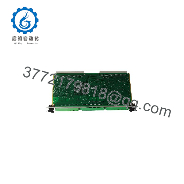
IOC4T 200-560-000-1130
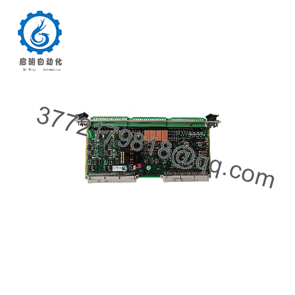
IOC4T 200-560-000-1130
Installation & Configuration Guide
Stage 1: Pre-Installation Preparation — Approximately 5–10 Minutes
⚠️ Safety First: Notify operations and place the machinery in the required safe state before working on the VM600 rack. Follow the site’s lockout/tagout procedure and verify that the rack is de-energized where the installation procedure requires power removal.
Tools Required:
- ESD wrist strap
- Suitable screwdriver
- Digital multimeter
- Wire labels
- Smartphone or camera for configuration records
- OEM wiring documentation
Data Backup:
- Record the complete part number and hardware revision from the existing .
- Record the installed MPC4 part number and revision.
- Photograph all terminal wiring before removal.
- Photograph any jumpers or configuration settings.
- Record existing relay and signal assignments.
- Keep the removed until the replacement has completed commissioning.
Critical check: Do not treat 200-560-000-1130 as automatically interchangeable with 200-560-000-113. The OEM documentation available for this product family specifically identifies 200-560-000-113 as an earlier version.
Stage 2: Removing the Old Module — Approximately 5 Minutes
- Confirm the rack is in the approved maintenance state.
- Label each field connection before disconnecting it.
- Disconnect the terminal wiring without pulling on the conductors.
- Release the module’s mechanical retention hardware.
- Pull the card straight out to avoid damaging the rack connector.
- Inspect the card edge and rack connector for contamination or mechanical damage.
⚠️ Do not discard the original card immediately. Its exact hardware revision and configuration may be required to resolve a compatibility problem.
Stage 3: Installing the New Module — Approximately 5–10 Minutes
- Put on the ESD wrist strap and connect it to a verified ground.
- Compare the replacement’s complete identification marking with the removed .
- Verify the mating MPC4 revision before installation.
- Transfer documented configuration settings where applicable.
- Carefully seat the into the VM600 rack.
- Secure the card according to the rack’s mechanical arrangement.
- Reconnect each terminal using the wiring photograph as the reference.
- Check that no conductor is loose or incorrectly landed.
Self-Checklist:
- Exact part number verified
- hardware revision recorded
- revision verified
- Wiring matched
- Configuration settings checked
- Card fully seated
- ESD precautions followed
Stage 4: Power-On & Testing — Approximately 10–15 Minutes
- Perform a final visual inspection before energizing the rack.
- Check for unintended shorts or wiring errors where applicable.
- Restore rack power according to the site’s commissioning procedure.
- Observe / status indications.
- Verify that the recognizes the installed I/O hardware.
- Confirm the four dynamic measurement channels.
- Verify the two tachometer channels.
- Check analog output values against the expected configuration.
- Test the assigned relay outputs using the approved commissioning procedure.
- Verify alarm and trip paths before returning the machinery to normal service.
⚠️ Compatibility warning: The OEM datasheet states that earlier versions including 200-560-000-113 have a 2,000 Ω buffered dynamic signal output, while later versions use 50 Ω. A replacement decision should therefore consider the installed revision and the complete card pairing, not only the physical dimensions.
Frequently Asked Questions (FAQ)
Can I use 200-560-000-1130 as a direct replacement for 200-560-000-113?
Do not assume that it is a direct replacement based solely on the model name. The OEM datasheet confirms 200-560-000-113, but I could not verify 200-560-000-1130 as an OEM ordering number. Match the complete label, hardware revision, and mating documentation before installation.
What does the do in a VM600 system?
The provides the physical I/O interface for an machinery protection card. The documented version provides four dynamic measurement inputs and two tachometer inputs, together with relay, analog, digital, and buffered raw-signal interfaces.
Is 200-560-000-113 different from later revisions?
Yes. Vibro-Meter’s datasheet identifies 200-560-000-113 and earlier as an earlier design group with a 2,000 Ω buffered dynamic signal output impedance. Later documented versions use 50 Ω. The change can affect replacement compatibility, so the / pair should be checked together.
Is the used with the ?
Yes. The OEM documentation identifies the as the input/output card for the machinery protection card in the system.
Can I hot-swap the ?
Do not rely on a general hot-swap claim for this exact part. The available OEM datasheet establishes the card’s interfaces and compatibility information but does not, in the cited material, provide sufficient evidence to authorize live insertion or removal. Follow the applicable installation procedure and site maintenance rules.
Is this an obsolete component?
The available documentation identifies the 200-560-000-113 version as an earlier design and documents later revisions. That does not by itself establish the commercial availability status of the requested 200-560-000-1130 marking. Confirm current OEM status and actual stock condition with the supplier before purchase.
Will replacing the erase the configuration?
The is an I/O interface card rather than the primary processing card. However, replacement still requires verification of the installed configuration, hardware revision, wiring, and compatibility. Photograph and document the existing installation before removing the card rather than assuming configuration details will transfer automatically.



