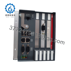
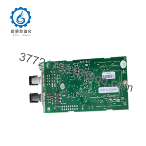
WhatsApp: +86 16626708626
 Email:
 Phone: +86 16626708626
Description
Core Product Summary
The VIBRO-METER VM600 IOC4T 200-560-000-113 is the input/output card that acts as the signal interface for the MPC4 machinery protection card in the VM600 series Mechanical Protection System (MPS) from Meggitt’s Vibro-Meter product line. It is installed in the rear of a VM600 rack, directly behind its associated MPC4 card, and connects to the rack backplane through two connectors, wiring the measurement chain signals into the protection system and the processed outputs back out to external control systems.
The card supports four dynamic signal inputs and two tachometer (speed) inputs for the MPC4, plus 32 fully programmable open-collector outputs. Signals from sensors and signal conditioners arrive through screw-terminal strip connectors on the card’s front panel (the rear of the rack), and processed dynamic signals are returned to the terminal strip, with four on-board digital-to-analog converters providing calibrated 0 to 10 V signal outputs. All inputs and outputs are protected against electromagnetic interference and signal surges in line with EMC requirements.
Key Technical Specifications
| Parameter | Value |
|---|---|
| Product type | Input/output card; signal interface for the VM600 MPC4 machinery protection card |
| System family | VIBRO-METER (Meggitt) VM600 MPS platform |
| Order number | 200-560-000-113 (IOC4T family; other 200-560 order codes denote other configurations of the card) |
| Installation | Rear of a VM600 rack (ABE04x or ABE056), directly behind its associated MPC4 card |
| Backplane connection | Two connectors, direct to the rack backplane |
| Operating mode | Slave mode; communicates with the MPC4 through connector P2 using an Industry Pack (IP) interface |
| Dynamic signal inputs | 4 per card, for the associated MPC4 |
| Tachometer (speed) inputs | 2, for the associated MPC4 |
| Outputs | 32 fully programmable open-collector outputs |
| Calibrated analog outputs | 4 on-board DACs providing calibrated signal outputs, 0 to 10 V range |
| Buffered “raw” dynamic signal outputs | Available at the screw-terminal connectors; output impedance 50 Ω; frequency response DC to 10 kHz (-0.1 dB with load >1 MΩ, -0.2 dB with load >200 kΩ), DC to 40 kHz at -3 dB |
| Buffered output phase error | <5° (DC to 1 kHz); <30° (DC to 10 kHz) |
| Buffered output transfer ratio | 1 V/V (voltage input); 0.3245 V/mA (current input) |
| Field wiring | Screw-terminal strip connectors on the card front panel for measurement chain cables and all external control system signal inputs and outputs |
| Protection | All inputs and outputs protected against electromagnetic interference and signal surges; conforms to EC EMC standards |
| Alarm reset | A closed contact between the DSI AR and DSI RET inputs clears the alarms latched by the MPC4/IOC4T card pair |
| Configuration | MPC4/IOC4T card pairs are configured and operated using the VM600 MPSx software |
Engineering Selection Highlights
- Fixed one-to-one pairing with the MPC4 — each IOC4T is associated with one MPC4 card and is mounted directly behind it in the rack (ABE04x or ABE056); the I/O capacity of a protection position is therefore defined by this card pair, not by the MPC4 alone.
- 4 dynamic + 2 tachometer inputs per card pair — the IOC4T defines how many measurement chains (sensors/signal conditioners) and speed signals each MPC4 position can accept, which is the constraint to count when planning channel allocation across a rack.
- 32 programmable open-collector outputs — a substantial output budget per card pair for alarm, status, and control signaling to external systems; outputs are programmable rather than fixed, so output assignment must be verified against the rack’s MPSx configuration.
- Four calibrated 0–10 V DAC outputs — processed dynamic signals can be re-exported as calibrated analog values, useful for feeding recorders, analyzers, or a DCS without tapping raw signals.
- EMI and surge protection on all I/O — the card’s front-end protection and EMC conformance matter in electrically noisy machine environments where signal lines share routes with power cables.
- Software scope boundary — MPC4/IOC4T pairs are configured with VM600 MPSx software and do not share their communication bus with XMx16/XIO16T condition monitoring card pairs in the same rack; mixed-function racks must plan each card family’s tooling separately.
- Order code precision — the 200-560 series includes multiple IOC4T configurations (for example, standard and separate-circuits versions); replacements should be matched by the complete order code rather than by the IOC4T name.
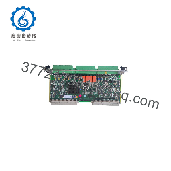
VM600 IOC4T 200-560-000-113
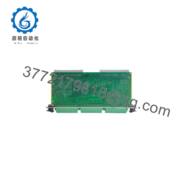
VM600 IOC4T 200-560-000-113
System Compatibility & Integration Requirements
| Item / Dependency | Verified Compatibility or Requirement | Practical Note |
|---|---|---|
| Companion card | MPC4 machinery protection card (VM600 series) | The IOC4T is mounted directly behind its associated MPC4 in the rack. |
| Rack | VM600 racks: ABE04x or ABE056 | The card installs at the rear of the rack in the slot behind the MPC4. |
| Backplane | Two direct connectors to the rack backplane | One of the connectors (P2) carries the Industry Pack interface to the MPC4. |
| Operating mode | Slave mode to the MPC4 | The IOC4T has no stand-alone protection function; it is the signal interface of the card pair. |
| Configuration software | VM600 MPSx software | MPC4/IOC4T pairs are configured and operated with MPSx; XMx16/XIO16T condition monitoring pairs in the same rack use separate tooling. |
| Field wiring | Screw-terminal strip connectors for measurement chain cables (sensors and/or signal conditioners) | The same terminal strips carry all signal inputs from and outputs to any external control system. |
| Alarm reset wiring | Closed contact between DSI AR and DSI RET inputs | Resets (clears) alarms latched by the MPC4/IOC4T card pair. |
| Functional safety use | VM600 functional safety manual covers MPC4/IOC4T use in functional safety contexts | Applicable when the card pair is deployed in safety-related machinery protection. |
| Buffered outputs | Raw dynamic signal outputs at the IOC4T screw-terminal connectors | Output impedance 50 Ω; may be shared with XMx16/XIO16T pairs but not with other MPC4/IOC4T pairs. |
Dimensions, Mounting & Connection Notes
- The IOC4T is a rear-of-rack card: it is installed in the VM600 rack (ABE04x or ABE056) in the slot directly behind its associated MPC4 card.
- The card connects to the rack backplane through two connectors and operates in slave mode, communicating with the MPC4 through connector P2 via an Industry Pack (IP) interface.
- All field wiring lands on terminal strip connectors on the card front panel (accessible at the rear of the rack): transmission cables from measurement chains (sensors and/or signal conditioners) on the input side, and all signals to and from external control systems on the output side.
- Buffered raw dynamic signal outputs are available at the screw-terminal connectors with 50 Ω output impedance.
- A closed contact between the DSI AR and DSI RET inputs provides alarm reset for the card pair.
- All inputs and outputs are filtered/protected against electromagnetic interference and signal surges and conform to EC EMC standards.
Detailed Product Overview
The VM600 IOC4T belongs to the card-pair architecture of the VM600 machinery protection system. In this architecture, protection intelligence and field interfacing are deliberately separated: the MPC4 card, at the front of the rack, performs the measurement processing and protection logic, while its associated IOC4T, mounted directly behind it at the rear, handles all physical signal connections. The 200-560-000-113 order number identifies one specific configuration of the IOC4T family.
The signal flow through the card is bidirectional and well-defined. From the measurement chains — sensors and/or signal conditioners — transmission cables land on the IOC4T’s terminal strips. The card passes these to the MPC4 through the Industry Pack interface over connector P2, operating in slave mode. Once the MPC4 has processed the signals, results return to the IOC4T and reappear at the terminal strip in three useful forms: as logic on the 32 programmable open-collector outputs, as calibrated analog values from the four on-board DACs in the 0–10 V range, and as buffered raw dynamic signal outputs. The buffered outputs deserve note for integration planning: with 50 Ω output impedance and flat response to 10 kHz, they can feed external analysis equipment directly, and they may be shared with XMx16/XIO16T condition monitoring card pairs in the same rack — but not with other MPC4/IOC4T pairs.
Input capacity per card pair is four dynamic signal inputs and two tachometer inputs. These numbers are what determine how many measurement positions one card pair covers, and they are the quantities to count when allocating channels across a protection scheme. The 32 open-collector outputs provide the opposite-side capacity: alarm, status, and command signaling to external systems, fully programmable so that the physical output map follows the MPSx configuration rather than fixed hardware positions.
Two operational details complete the picture. First, alarm handling: a closed contact between the DSI AR and DSI RET inputs clears all alarms latched by the card pair — a rack-level wiring feature that lets an external control system reset protection alarms without software access. Second, configuration discipline: MPC4/IOC4T pairs are configured and operated with the VM600 MPSx software, and the same rack can host XMx16/XIO16T condition monitoring pairs that use different tooling and do not share the protection pairs’ communication bus. For functional safety deployments, the manufacturer provides a dedicated VM600 functional safety manual covering MPC4/IOC4T use, which is the reference document for SIL-rated machinery protection applications.
For procurement, the ordering landscape matters. The IOC4T family spans multiple 200-560 order codes — including standard and separate-circuits versions — and the digit groups of 200-560-000-113 encode the delivered configuration. A replacement or expansion card should be matched by its complete order code, with the card then verified in the rack behind its MPC4 and its signal and alarm functions checked per the commissioning procedure before return to service.
Applications & System Role
The IOC4T occupies the field-wiring layer of a VM600 machinery protection position. Its role is to be the terminal point of the measurement chain: dynamic signals from vibration sensors and signal conditioners, tachometer signals for speed measurement, and external control system contacts all land on its terminal strips, and it passes these to its MPC4 protection card for processing through the Industry Pack interface on the rack backplane. In the reverse direction, the MPC4’s processed results — alarm and status logic on the open-collector outputs, calibrated 0–10 V analog representations of dynamic signals from the on-board DACs, and buffered raw signal outputs — are made available on the same terminal strips for external systems.
The card pair architecture is the defining characteristic. An MPC4 without its IOC4T has no field signal interface, and each IOC4T serves exactly one MPC4. This makes the IOC4T a necessary line item whenever an MPC4 protection position is added or replaced, and a common spare for VM600 MPS installations where protection positions are maintained at the card-pair level.
As part of a machinery protection system, typical signal sources for a card pair are dynamic vibration measurement chains and speed/tachometer signals from rotating equipment monitoring, with outputs feeding alarm annunciators, DCS/SCADA inputs, and shutdown or event-logging systems — the specific assignment being defined in the MPSx configuration rather than by fixed hardware wiring.
FAQ
What is the VIBRO-METER VM600 IOC4T 200-560-000-113?
It is an input/output card from the Meggitt Vibro-Meter VM600 series that acts as the signal interface for the MPC4 machinery protection card, installed in the rear of a VM600 rack directly behind its associated MPC4.
What inputs and outputs does it provide?
Four dynamic signal inputs and two tachometer (speed) inputs for the MPC4, plus 32 fully programmable open-collector outputs and four on-board DACs providing calibrated 0 to 10 V analog signal outputs.
How does it connect to the MPC4?
It operates in slave mode and communicates with the MPC4 through connector P2 using an Industry Pack (IP) interface across the rack backplane.
Which racks does it fit?
It is installed at the rear of VM600 system racks (ABE04x or ABE056), in the slot directly behind the corresponding MPC4 card, connecting to the backplane via two connectors.
How are field signals wired?
Through screw-terminal strip connectors on the card’s front panel (the rear of the rack), which carry both the measurement chain cables from sensors and signal conditioners and all signals to and from external control systems.
How are alarms reset on the card pair?
A closed contact between the DSI AR and DSI RET inputs resets (clears) the alarms latched by the MPC4/IOC4T card pair.
Which software configures it?
MPC4/IOC4T card pairs are configured and operated using the VM600 MPSx software; the VM600 functional safety manual applies when the card pair is used in functional safety contexts.
Can it replace any IOC4T card?
Not by name alone — the 200-560 order series includes multiple IOC4T configurations, so replacements should be matched by the complete order code and verified against the rack configuration.