
 WhatsApp: +86 16626708626
 Email:
 Phone: +86 16626708626
Description
Core Product Summary
The VIBRO-METER VM600 MPC4 (order codes 200-510-071-113 and 200-510-111-034, from the 200-510 order series) is the central machinery protection card of the VM600 series Machinery Protection System (MPS) from Meggitt’s Vibro-Meter product line. It is a continuously online protection card that measures and monitors up to four dynamic signal inputs and two speed (tachometer) inputs simultaneously, using real-time digital signal processing to evaluate vibration and position parameters against programmable protection limits.
Each dynamic channel is individually programmable and accepts signals representing acceleration, velocity, or displacement (proximity), among others, allowing measurement of relative and absolute vibration, Smax, eccentricity, thrust position, housing expansion, and dynamic pressure. Digital processing includes filtering, integration or differentiation, rectification (RMS, mean value, true peak or true peak-to-peak), and order tracking with simultaneous amplitude and phase monitoring. Alert, Danger, and OK set points are fully programmable with adaptive levels, and alarm outputs drive relays on the paired IOC4T card or optional RLC16/IRC4 relay cards.
Key Technical Specifications
| Parameter | Value |
|---|---|
| Product type | Continuously online machinery protection card (DSP-based) |
| System family | VIBRO-METER (Meggitt) VM600 MPS platform |
| Order codes | 200-510-071-113 / 200-510-111-034 (MPC4 order series 200-510-SSS-xHh) |
| Dynamic signal channels | 4 per card, all individually programmable |
| Tachometer (speed) channels | 2 |
| Accepted dynamic signal types | Acceleration, velocity, displacement (proximity), among others |
| Measurable physical parameters | Relative and absolute vibration, Smax, eccentricity, thrust position, absolute and differential housing expansion, displacement, dynamic pressure |
| Digital processing | Digital filtering; integration or differentiation; rectification (RMS, mean value, true peak, true peak-to-peak); order tracking (amplitude and phase); sensor-target gap measurement |
| Filters | Programmable broad-band and narrow-band filters |
| Order tracking | Simultaneous amplitude and phase monitoring |
| Set points | Programmable Alert, Danger, and OK set points; adaptive Alert and Danger levels; programmable alarm time delay, hysteresis, and latching; levels can be a function of speed or external information |
| Units | Metric or imperial |
| Speed sensor types | Proximity probes, magnetic pulse pickup sensors, TTL-based systems; fractional tachometer ratios supported |
| Dynamic input ranges | DC: 0 to +20 V or 0 to −20 V; AC: ±10 V max.; current input: DC 0 to 25 mA, AC ±8 mA max. |
| Input characteristics | Common mode voltage range −50 to +50 V; CMRR >60 dB at 50 Hz; crosstalk −72 dB; input impedance 200 kΩ; current measuring resistor 324.5 Ω |
| Analog frequency range | DC to 60 kHz (−3 dB) |
| Analog AC frequency range | 0.1 Hz to 10 kHz without integration; 2.5 Hz to 10 kHz with integration |
| Buffered raw signal outputs | Front-panel BNC connectors (MPC4) and screw-terminal connectors (IOC4T); output impedance 50 Ω; DC to 10 kHz (−0.1 dB with load >1 MΩ); DC to 40 kHz at −3 dB |
| Buffered output phase error | <5° (DC to 1 kHz); <30° (DC to 10 kHz) |
| Buffered output transfer ratio | 1 V/V (voltage input); 0.3245 V/mA (current input) |
| Alarm outputs | Digital output per alarm level on the corresponding IOC4T; four local relays on the IOC4T and/or routing via the rack’s Raw bus or Open Collector (OC) bus to optional RLC16 or IRC4 relay cards |
| Processed analog outputs | Dynamic (vibration) and speed signals at the rear of the rack (IOC4T front panel); voltage-based 0 to 10 V and current-based 4 to 20 mA |
| Diagnostics | Self-test and diagnostic routine on power-up; built-in “OK system” continuously monitors measurement chain signal levels (broken transmission line, faulty sensor or signal conditioner); front-panel LED indicates processing or hardware errors |
| Front panel | BNC connectors for buffered raw sensor signals; LEDs indicating status and alarms |
| Safety certification | Standard MPC4 (PNR 200-510-071-113) is safety certified; standard and SIL versions certified for SIL 1 per IEC 61508 and PL c per ISO 13849-1 |
| Version family | Standard (200-510-SSS-1Hh), separate circuits (200-510-SSS-2Hh), safety MPC4SIL (200-510-SSS-3Hh) |
Engineering Selection Highlights
- 4 dynamic + 2 tachometer channels, all individually programmable — one MPC4/IOC4T card pair covers a four-point vibration measurement scheme plus two speed or phase reference signals, with per-channel signal type and processing configured independently.
- Multi-parameter processing from one card — on-board processing derives Smax, eccentricity, thrust position, housing expansion, and dynamic pressure in addition to vibration, so a single card can serve several protection functions on one machine train.
- Programmable protection logic — Alert, Danger, and OK set points with adaptive levels, time delays, hysteresis, latching, and speed-dependent alarm levels allow the protection behavior to follow the machine’s operating envelope rather than fixed limits.
- Order tracking with amplitude and phase — simultaneous amplitude/phase monitoring in order-tracking mode supports vectorial monitoring of 1× and higher orders, which is essential for turbine and compressor protection schemes.
- Fixed IOC4T pairing — the card functions as a card pair with a corresponding IOC4T input/output card; the IOC4T provides field signal termination, the four local relays, and the processed analog outputs, so every MPC4 position must budget its paired IOC4T.
- Relay expansion via rack buses — when the IOC4T’s four local relays are insufficient, alarm signals route over the rack’s Raw bus or Open Collector bus to optional RLC16 or IRC4 relay cards, defining the path for larger trip and alarm contact schemes.
- MPS/CMS segregation per API 670 — MPC4/IOC4T pairs are configured and operated with the VM600 MPSx software and do not share communication buses with XMx16/XIO16T condition monitoring pairs (which use VibroSight), protecting the independence of the protection function.
- Version selection matters — the MPC4 exists in standard, separate-circuits, and SIL (MPC4SIL) versions; the SIL version omits the VME slave interface and tachometer channels to achieve isolation in mixed racks, so the version must match the safety architecture.
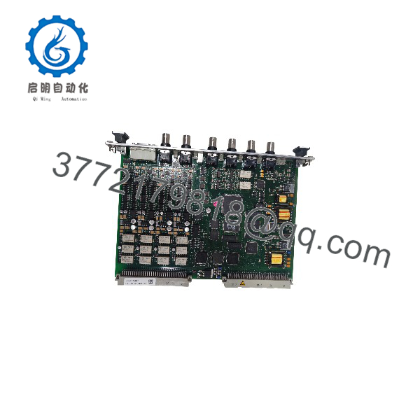
VM600 MPC4 200-510-071-113 200-510-111-034
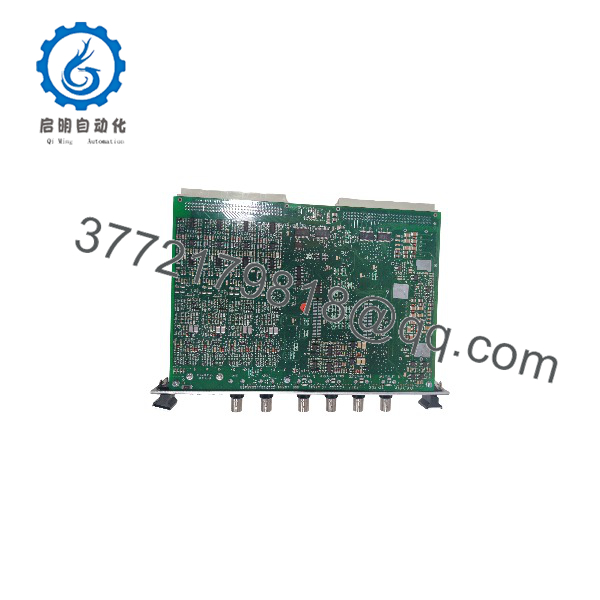
VM600 MPC4 200-510-071-113 200-510-111-034
System Compatibility & Integration Requirements
| Item / Dependency | Verified Compatibility or Requirement | Practical Note |
|---|---|---|
| Companion card | IOC4T input/output card | The MPC4 functions as a card pair with a corresponding IOC4T; the IOC4T carries field wiring, four local relays, and the processed analog outputs. |
| Rack | VM600 ABE04x system racks and ABE056 slimline rack | The card pair installs in standard VM600 racks. |
| Configuration | VM600 MPSx software, via a CPUx/IOCx rack controller card pair over the VME bus, or via the card’s RS-232 front-panel connector | The standard MPC4 has a VME-compatible slave interface, software configurable over VME when a CPUx card is present in the rack. |
| Relay cards | RLC16 or IRC4 optional relay cards | Alarm signals route via the rack’s Raw bus or Open Collector bus when more than the IOC4T’s four local relays are needed. |
| Condition monitoring coexistence | XMx16/XIO16T card pairs | Protection and condition monitoring pairs share no communication buses; each family is configured with its own software (MPSx vs. VibroSight), per API 670 MPS/CMS segregation. |
| Raw signal sharing | Buffered raw dynamic signal outputs can be shared with XMx16/XIO16T pairs but not with other MPC4/IOC4T pairs | Relevant when the same measurement chain feeds both protection and monitoring functions. |
| Functional safety | VM600 functional safety manual; standard and SIL versions certified SIL 1 (IEC 61508) and PL c (ISO 13849-1) | The SIL version (MPC4SIL) omits the VME slave interface and tachometer channels for isolation in mixed racks. |
| Sensor types | Proximity probes, velocity sensors, accelerometers, magnetic pulse pickups, TTL-based speed signals | Signal type is configured per channel; sensor-target gap measurement is included for proximity channels. |
Detailed Product Overview
The VM600 platform assigns its protection function to a card pair: the MPC4 machinery protection card, which measures and decides, and the IOC4T input/output card, which terminates field wiring and delivers outputs. The MPC4 is explicitly described by the manufacturer as the central element of the VM600 machinery protection system, and its architecture reflects that role — everything on the card exists to turn sensor signals into protection decisions continuously and online.
The signal path begins with four fully programmable dynamic channels. Each accepts signals representing acceleration, velocity, or displacement, among others, with input ranges covering DC to ±20 V, AC to ±10 V, and current inputs to 25 mA, over a frequency span reaching 60 kHz at the −3 dB point. Input quality is engineered for measurement integrity: common-mode rejection above 60 dB at 50 Hz, crosstalk at −72 dB, and 200 kΩ input impedance. Per-channel programming extends to the processing applied: digital filtering with programmable broad-band and narrow-band characteristics, integration or differentiation for unit conversion between acceleration, velocity, and displacement, and rectification selectable as RMS, mean value, true peak, or true peak-to-peak — the choice that determines what “amplitude” means for each monitored parameter.
Two tachometer channels complete the measurement set, accepting proximity probes, magnetic pulse pickups, or TTL signals, with fractional tachometer ratios supported for geared train configurations. The speed inputs enable the card’s order-tracking mode, in which amplitude and phase are monitored simultaneously on machine orders — the basis for vectorial monitoring that distinguishes load-related vector changes from genuine vibration growth.
Protection logic is where the card’s flexibility concentrates. Alert, Danger, and OK set points are fully programmable, with alarm time delay, hysteresis, and latching behavior configurable per alarm. Alert and Danger levels can be adaptive and can be made a function of machine speed or external information, so a protection envelope can follow the machine’s operating region. Configuration is expressed in metric or imperial units, and is performed through the VM600 MPSx software — either over the VME bus when a CPUx rack controller is present, or directly through the card’s front-panel RS-232 connector.
Alarm execution follows a two-tier output model. Each alarm level has an internal digital output on the corresponding IOC4T, and these signals can drive the IOC4T’s four local relays, or route across the rack’s Raw bus or Open Collector bus to optional relay cards (RLC16 or IRC4) when a scheme needs more trip and alarm contacts. Processed vibration and speed signals re-emerge at the rear of the rack as 0–10 V and 4–20 mA analog outputs on the IOC4T, feeding DCS and recording systems. Buffered raw sensor signals are available both at front-panel BNC connectors and at the IOC4T terminals — with one architectural rule worth remembering: raw dynamic outputs may be shared with XMx16/XIO16T condition monitoring pairs, but not with other MPC4/IOC4T pairs.
Version selection deserves engineering attention. The order series 200-510-SSS-xHh defines three versions: standard, separate circuits, and safety (MPC4SIL). The standard card — including PNR 200-510-071-113 — is safety certified, with the standard and SIL versions carrying SIL 1 (IEC 61508) and PL c (ISO 13849-1) certification. The MPC4SIL was developed for mixed racks containing condition monitoring and relay cards: it omits the VME-compatible slave interface and the tachometer channels and does not provide all of the standard card’s processing, specifically so its configuration cannot be inadvertently modified from elsewhere in the rack. Finally, the platform’s API 670 segregation discipline applies throughout: protection and condition monitoring card pairs share no communication buses, keeping the protection function independent of monitoring operations.
For procurement, the two order codes in the listing — 200-510-071-113 and 200-510-111-034 — belong to the MPC4’s 200-510 order series, whose digit groups encode the delivered version and configuration. Replacements should be matched by complete order code, paired with the correct IOC4T version, and verified after installation per the commissioning procedure before the protection position is returned to service.
Applications & System Role
The MPC4 sits at the protection layer of a VM600 rack: it is the card that continuously measures machinery signals, evaluates them against configured protection limits, and raises alarms and trip contacts when limits are violated. In a typical installation, one MPC4/IOC4T card pair protects one machine or machine section — its four dynamic channels covering radial vibration and position measurements, and its two tachometer channels providing the speed and phase references needed for order tracking and speed-dependent alarm levels.
The card’s processing breadth means it serves both simple and complex protection schemes. At the simple end, it monitors plain broadband vibration levels with fixed Alert and Danger limits. At the complex end, it performs filtered narrow-band measurements, rectification modes from RMS to true peak-to-peak, order-tracked amplitude and phase, and multi-parameter machine supervision including eccentricity, thrust position, and differential expansion — the measurement set required for turbine supervisory protection.
The built-in “OK system” and power-up self-test give the card its chain-integrity role: it continuously confirms that each measurement chain is healthy, so a broken transmission line or faulty sensor is detected and indicated rather than silently misread as good vibration behavior. Front-panel LEDs, BNC access to buffered raw signals, and the error LED support the commissioning and troubleshooting workflow at the rack.
FAQ
What is the VIBRO-METER VM600 MPC4?
It is the central machinery protection card of the VM600 series MPS — a continuously online protection card that measures and monitors up to four dynamic signal inputs and two speed inputs simultaneously using real-time DSP techniques.
What order codes does it use?
MPC4 cards are ordered under 200-510-series codes (format 200-510-SSS-xHh); 200-510-071-113 and 200-510-111-034 are order codes within this family.
What can each dynamic channel measure?
Channels are individually programmable for acceleration, velocity, and displacement (proximity) signals, and the card’s processing supports relative and absolute vibration, Smax, eccentricity, thrust position, absolute and differential housing expansion, displacement, and dynamic pressure.
Which card must be paired with it?
A corresponding IOC4T input/output card; the IOC4T terminates field wiring, provides four local alarm relays, and outputs the processed signals as 0–10 V and 4–20 mA.
How are alarms and trips handled?
Alert, Danger, and OK set points are programmable with adaptive levels, time delays, hysteresis, and latching; alarm signals drive the IOC4T’s relays and/or route via the rack’s Raw bus or Open Collector bus to RLC16 or IRC4 relay cards.
How is the card configured?
With the VM600 MPSx software, either over the rack’s VME bus via a CPUx rack controller card or through the card’s front-panel RS-232 connection.
What diagnostics does it provide?
A self-test and diagnostic routine runs at power-up, and the built-in OK system continuously monitors measurement chain signal levels to detect broken transmission lines or faulty sensors or signal conditioners; a front-panel LED indicates processing or hardware errors.
Is it certified for functional safety use?
The standard MPC4 (PNR 200-510-071-113) is safety certified, and both the standard and SIL versions are certified for SIL 1 per IEC 61508 and PL c per ISO 13849-1; the VM600 functional safety manual governs safety-related deployment.



