WhatsApp: +86 16626708626
 Email:
 Phone: +86 16626708626
Description
Core Product Summary (Brand / Model / Key Attributes)
The Vibro-Meter VM600 RLC16 (Meggitt) is a 16-channel relay expansion module set engineered for the VM600 machinery protection system. Installed within VM600 ABE60x series 19-inch racks, this matched hardware pair consists of the front-processing RLC16 Relay Local Card (P/N: 200-570-000-111) and the corresponding rear-mounting IRC16 / IOC Terminal Module (P/N: 200-570-101-015).
Operating across the internal VMEbus and raw relay logic buses, the RLC16 module pair expands the physical relay output capacity of the VM600 rack. It receives alarm, danger, and system status signals evaluated by primary machinery protection cards (such as the MPC4) and drives 16 independent, fully programmable relay contacts for plant Emergency Shutdown Systems (ESD), trip interlocks, and local annunciators.
Key Technical Specifications
| Parameter | Specification |
| Manufacturer | Vibro-Meter (Meggitt Sensing Systems) |
| Model Designation | VM600 RLC16 (Relay Local Card Pair) |
| Front Module Part Number | 200-570-000-111 (RLC16 Front Card) |
| Rear Module Part Number | 200-570-101-015 (IRC16 / IOC Rear Terminal Card) |
| System Platform | VM600 Machinery Protection System |
| Relay Output Channels | 16 independent SPDT (Single Pole Double Throw / Form C) mechanical relays |
| Contact Rating (AC) | 250 V AC max; 5 A max (resistive load) |
| Contact Rating (DC) | 30 V DC max; 5 A max / 220 V DC max (power-limited) |
| Relay Configuration | Software programmable: Normally Energized (Fail-Safe) / Normally De-Energized; Latching / Non-Latching |
| Logic Interlocks | Configurable Voting Logic (e.g., 1-out-of-2, 2-out-of-3, AND/OR matrix combinations) |
| Power Consumption | Powered via VM600 VMEbus backplane (+5V DC / +12V DC) |
| Form Factor | 6U Eurocard format (Front Card: 262 mm × 20 mm × 187 mm) |
| Operating Temperature Range | -20°C to +65°C (-4°F to +149°F) |
| Relative Humidity | 0% to 95% non-condensing |
| Environmental Approvals | CE marked, safety-certified (SIL scope capable per system design) |
Detailed Product Overview
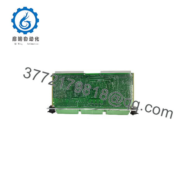
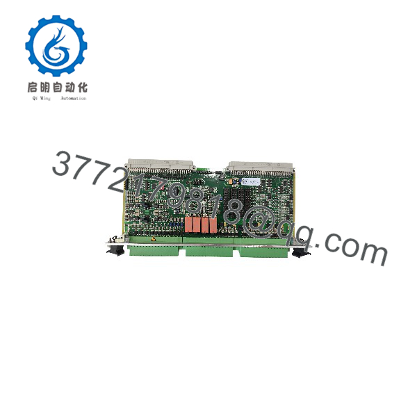
The Vibro-Meter VM600 RLC16 (200-570-000-111 / 200-570-101-015) card set serves as an auxiliary machinery protection output interface within the VM600 rack platform. While processing modules like the MPC4 contain internal relays, complex industrial installations—such as multi-bearing steam turbines, gas turbines, and multi-stage compressors—often require additional discrete relay dry contacts to drive complex shutdown logic matrices across plant Distributed Control Systems (DCS) and Safety Instrumented Systems (SIS).
The RLC16 card set functions as a synchronized front and rear pair across the VM600 backplane:
- Front RLC16 Card (200-570-000-111): Contains the onboard microprocessor, relay control logic, VMEbus communication interface, and 16 physical electromechanical relay assemblies.
- Rear Card (200-570-101-015): Installs directly behind the RLC16 in the rear rack plane, exposing heavy-duty, plug-in screw terminal blocks for field wiring landing (NO, NC, and Common terminals for all 16 channels).
Using Vibro-Meter MPS / VibroSight software, each of the 16 relays can be mapped to specific channel alarm combinations, system health states, or voting logic routines. Onboard status LEDs on the front panel provide real-time visual verification of active relay coil states.
VM600 RLC16 200-570-000-111 200-570-101-015
VM600 RLC16 200-570-000-111 200-570-101-015
Engineering Selection Highlights
- 16 High-Capacity Output Relays: Expands VM600 discrete output capabilities with 16 dry-contact SPDT relays rated for industrial switching loads.
- Matched Front/Rear Pair: Ordering combination (200-570-000-111 front card + 200-570-101-015 rear module) delivers a complete functional slot build.
- Flexible Logic Mapping: Integrates via software to execute complex voting schemes (1-out-of-2, 2-out-of-3) combining inputs from multiple MPC4 cards across the rack.
- Fail-Safe Operation: Relays can be configured for normally energized mode, ensuring an immediate trip signal is triggered if system power is lost.
- Rear Wiring Isolation: All high-voltage/high-current field relay wiring lands on the rear 200-570-101-015 terminal module, protecting sensitive front-plane digital processing logic.
System Compatibility & Integration Requirements
| Item / Dependency | Verified Compatibility or Requirement | Practical Note |
| Mainframe Chassis | Vibro-Meter VM600 ABE60x 19″ Racks | Installs into standard 6U front and rear matching slots |
| Companion Processing Cards | VM600 MPC4 / AMC8 Protection Modules | Receives alarm signals evaluated by protection cards via backplane logic |
| System Controller | VM600 CPUx / CPUM Controller | Configured and managed via rack VMEbus communications |
| Software Interface | Vibro-Meter MPS / VibroSight Software Suite | Used to program relay allocation, voting logic, and coil energization modes |
| External Interlocks | Plant ESD, DCS, and PLC Safety Circuits | Contacts wire directly to plant shutdown and alarm loops |
Dimensions, Mounting & Connection Notes
- Form Factor: Standard 6U Eurocard format.
- Dimensions (Front Card): Height: 262 mm (10.3 in) | Width: 20 mm (0.8 in) | Depth: 187 mm (7.4 in).
- Mounting: The front card (200-570-000-111) slides into the front slot of a VM600 19-inch rack; the rear card (200-570-101-015) slides into the exact matching rear slot. Both are secured with captive thumbscrews.
- Field Wiring Connections: External control wires land on high-density removable screw terminal blocks on the rear 200-570-101-015 card faceplate.
- Grounding: Functional earthing is established automatically through the rack frame when retaining screws are securely tightened.
FAQ
What is the difference between part numbers 200-570-000-111 and 200-570-101-015?
Part number 200-570-000-111 refers to the front-side RLC16 processing and relay card, while 200-570-101-015 refers to the matching rear I/O terminal card where external field relay wiring terminates.
Can the RLC16 operate as a standalone module without protection cards?
No. The RLC16 is a relay expansion card that requires primary machinery protection modules (like the MPC4) and system software mapping to trigger its outputs.
Are the relay outputs on the RLC16 configurable for fail-safe operation?
Yes. Each relay can be independently programmed as “Normally Energized” (fail-safe, de-energizes on trip or power loss) or “Normally De-Energized” via configuration software.
What type of contact outputs are provided?
The module provides 16 Single Pole Double Throw (SPDT / Form C) mechanical dry contacts, offering both Normally Open (NO) and Normally Closed (NC) terminals for each channel.
Verification & Troubleshooting Notes
High-Voltage Interlock Hazard
Always isolate external AC/DC control circuit power landed on the rear 200-570-101-015 terminal block before installing, removing, or touching relay output connections to avoid electrical shock or accidental machine trips.
1.Inspect Front-Panel LED Indicators:1 min.
Observe the LED diagnostic indicators on the front panel of the 200-570-000-111 card upon applying rack power.
Verification: The green status/health LED lights solid green, and individual channel LEDs reflect the expected state (lit for energized coils).
2.Verify Front and Rear Module Seating:2 min.
If the RLC16 card displays backplane communication errors, switch off rack power, loosen all captive thumbscrews, and firmly re-seat both the 200-570-000-111 front card and 200-570-101-015 rear card into their respective slots.
Verification: Module faceplates fit flush against the rack frame rail, and backplane pin headers engage smoothly without resistance.
3.Perform Relay Contact Continuity Test:3 min.
With external trip power isolated, trigger a manual test/alarm state using Vibro-Meter MPS software for a designated channel. Measure continuity across the corresponding NO/NC screw terminals on the rear 200-570-101-015 card using a digital multimeter.
Verification: The contact state toggles cleanly between open (infinity) and closed (less than 1 ohm) upon software activation.
4.Check Configuration Logic Assignment:2 min.
If a relay fails to actuate during a machine alarm event, open the MPS configuration software and verify that the specific RLC16 channel is properly mapped to the intended MPC4 input channel and voting matrix.
Verification: The software mapping matrix correctly assigns the input channel alarm condition to the designated RLC16 relay output number.