WhatsApp: +86 16626708626
 Email:
 Phone: +86 16626708626
Description
Key Technical Specifications
The following specifications are drawn from Warner Electric MCS2000 documentation and associated product references. Confirm the exact controller revision and configuration before installation.
| Parameter | Value |
|---|---|
| Manufacturer | Warner Electric |
| Product family | MCS2000 Modular Control Components |
| Model | MCS2000-ECA |
| Associated part number | 6910-448-096 |
| Product category | Digital tension controller |
| Supply voltage | 24 VDC ±5% |
| Typical supply current | 0.2 A |
| Analog inputs | 2 |
| Standard analog input range | 0–10 VDC |
| Sensor input | ±10 VDC; minimum differential of 4 V |
| Analog outputs | 2 controlled channels |
| Programmable analog output ranges | ±10 VDC or 0–20 mA |
| Open-loop output | 0–10 VDC |
| Voltage reference output | +10 VDC, 10 mA maximum |
| Sensor supply | ±15 VDC, 100 mA maximum |
| Digital outputs | 2 binary sensor-level indication outputs |
| Communication interface | RS-232 |
| Control modes | Open-loop, closed-loop, and combined open-loop with superimposed closed-loop control |
| Program storage | Plug-in memory card stores up to two complete programs |
| Programming options | Dedicated programming tool, optional display, Windows software, or terminal-mode communication |
| Mounting | Wall mounting inside a fan-cooled control cabinet |
| Lifecycle status | Legacy; verify current OEM support |
Specification note: The controller’s available functions depend on its configuration and associated equipment. Do not assume that every analog range, programming accessory, or control mode is enabled in every installation.
Product Introduction & Supply Chain Strategy
The Warner Electric MCS2000-ECA is a programmable digital controller designed for industrial tension regulation. It supports open-loop and closed-loop control and provides two analog output channels for integration with compatible tension-control equipment. Typical applications include paper converting, film processing, printing, and other continuous-web operations.
For legacy machinery, verified new-surplus inventory can reduce replacement lead-time risk when standard distribution channels cannot supply the required component. Evaluate Total Cost of Ownership (TCO), condition evidence, programming-tool availability, and warranty coverage. Set buffer stock according to equipment criticality and actual replenishment lead time rather than purchasing excess inventory without a defined demand or obsolescence strategy.
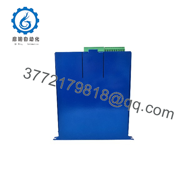
MCS2000-ECA
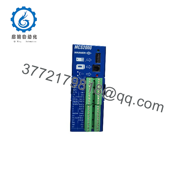
MCS2000-ECA
Installation & Configuration Guide
The MCS2000-ECA requires application-specific programming and appropriate sensor and output configuration. Warner Electric documentation identifies dedicated programming tools, optional display hardware, Windows programming software, and terminal-mode communication as available programming methods.
Stage 1: Pre-Installation — Preparation and Safety
- Verify the identification: Confirm MCS2000-ECA and part number 6910-448-096 against the existing controller’s nameplate.
- Apply lockout/tagout: Isolate the relevant machine and electrical supplies according to plant procedures.
- Record existing settings: Back up the tension-control program, setpoints, sensor scaling, output configuration, and control mode.
- Document wiring: Photograph terminal connections and label each sensor, command, and output conductor.
- Prepare ESD protection: Use suitable antistatic handling procedures when handling electronic assemblies.
Stage 2: Removal
- Confirm that the machine is in a safe state and that stored mechanical energy has been controlled.
- Verify electrical isolation before disconnecting the controller.
- Label and remove wiring according to the approved maintenance procedure.
- Release the mounting hardware and remove the controller without stressing its terminals or connectors.
- Inspect the cabinet, wiring, grounding, and ventilation for damage or contamination.
Stage 3: Installation — Mount and Connect
- Confirm the replacement’s part number and terminal arrangement before installation.
- Mount the controller in the approved enclosure, maintaining the ventilation clearances specified in the manual.
- Reconnect the 24 VDC supply, analog signals, sensor connections, and control outputs according to the original wiring documentation.
- Verify signal polarity and distinguish voltage signals from current-loop signals before energizing.
- Check grounding, terminal tightness, and wiring separation before closing the cabinet.
Stage 4: Power-On and Functional Testing
- Measure the supply voltage and confirm it falls within the documented 24 VDC ±5% range.
- Energize the controller following the approved commissioning procedure.
- Connect the appropriate programming interface and verify access to the controller’s configuration.
- Restore the approved program and confirm sensor scaling, setpoints, control mode, and output limits.
- Test the sensor input and both analog output channels under controlled conditions.
- Verify tension response at low operating speed before returning the machine to normal production.
- Record the final configuration and commissioning results.
Important: Do not assume the MCS2000-ECA can be hot-swapped. Confirm the machine’s safe-state requirements and the manufacturer’s approved replacement procedure before removing the installed controller.
Firmware/Software Versions & Upgrade Notes
The available documentation describes the MCS2000-ECA’s programming methods and control functions but does not establish a single recommended firmware revision applicable to every installation.
- Recommended version: Verify the installed controller’s revision and the applicable Warner Electric documentation before selecting replacement hardware or programming software.
- Programming compatibility: Confirm that the available programming tool or software supports the target controller and its communication interface.
- Program backup: Save the existing control program and document sensor calibration, setpoints, output limits, and operating mode before replacement.
- Memory-card handling: The controller supports a plug-in memory card for program storage. Verify card compatibility and the program-restoration procedure before relying on it as the sole backup.
- Communication interface: The standard documented interface is RS-232. Confirm the correct cable, communication settings, and software before attempting configuration access.
- Upgrade and downgrade risks: Do not apply firmware or software changes without verified version compatibility. An unsupported change can affect commissioning, program transfer, or control behavior.
- Legacy-system planning: If programming accessories or software are difficult to source, consider securing compatible tools and verified program backups alongside the replacement controller.
For procurement, request the hardware identification, available revision information, and confirmation of any included programming accessories. These details can determine whether the controller can be commissioned without additional sourcing delays.
Frequently Asked Questions (FAQ)
Q1. What is the Warner Electric used for?
The is a digital tension controller for industrial machinery handling continuous materials. It regulates tension through configurable open-loop and closed-loop control and interfaces with compatible sensors and control equipment.
Q2. What is the correct part number for the ?
The associated part number is 6910-448-096. Confirm this number against the controller’s physical nameplate and the applicable manufacturer documentation before ordering.
Q3. Is the available as new-original or new-surplus inventory?
Availability depends on the supplier’s current stock. Ask for clear photographs of the actual unit, its nameplate and part number, condition documentation, and written confirmation of the warranty.
A catalog listing or stock photograph alone does not establish that a specific unit is new or authentic.
Q4. Is the discontinued?
Some industrial-parts listings classify the model as discontinued, but current official lifecycle status has not been independently confirmed. Contact the manufacturer or an authorized support channel to verify availability and any recommended replacement.
If the unit is no longer supported, assess last-time-buy options and the availability of compatible programming equipment before the existing stock is exhausted.
Q5. Can I replace the without changing the machine’s control program?
Potentially, but this depends on the replacement’s compatibility and the condition of the existing program backup. Verify the controller revision, sensor scaling, control mode, output configuration, and programming interface. Commission the replacement under controlled operating conditions before returning the machine to production.
Q6. Does the support RS-232 communication?
Yes. Manufacturer documentation identifies RS-232 communication and describes programming through dedicated tools, Windows software, or terminal-mode communication. Confirm the required interface hardware and software compatibility before commissioning.
Q7. What warranty should I expect when purchasing a new-surplus ?
Warranty terms depend on the supplier and should be confirmed in writing. Verify the coverage period, start date, return procedure, and remedies for a confirmed defect. Request documented confirmation of the supplied unit’s condition and any inspection or functional-test records.