
 WhatsApp: +86 16626708626
 Email:
  Phone: +86 16626708626
Description
Key Technical Specifications
| Parameter | Value |
|---|---|
| Manufacturer | Watlow Anafaze |
| Base Model | CLS216 |
| Product Family | CLS200 Compact Loop System |
| Product Type | Multi-loop PID temperature and process controller |
| Maximum Control Loops | 16 |
| Input Channels | Up to 16 analog process-input channels, configuration-dependent |
| Supported Input Types | Thermocouples, RTDs, linear voltage, linear current, and frequency inputs |
| Control Methods | PID and on/off control; feature set depends on installed firmware |
| Available Firmware Types | Standard, ramp/soak, and enhanced control options, configuration-dependent |
| Control Outputs | Configuration-dependent relay, SSR/logic, analog, and other output arrangements |
| Digital Inputs | Up to 8, configuration-dependent |
| Digital Outputs | Up to 34 with mass-termination configuration, configuration-dependent |
| Process Setup Storage | Up to 8 stored jobs/recipes reported for applicable configurations |
| Serial Communications | EIA/TIA-232 and EIA/TIA-485 |
| Serial Protocol Options | Modbus RTU or Anafaze protocol, configuration-dependent |
| Scan Rate | Approximately 1.5 samples per second per channel |
| A/D Resolution | 14-bit conversion, as reported for CLS216 configurations |
| Measurement Accuracy | Approximately 0.1% of span, configuration and sensor dependent |
| Supply Requirement | Exact supply is suffix-dependent; verify the complete nameplate and wiring diagram before ordering |
| Mounting | Panel-mount multi-loop controller; confirm actual cutout, bezel, and rear depth from the installed unit |
| Replacement Requirement | Match full model suffix, input type, output architecture, firmware, communication protocol, supply voltage, terminal hardware, and stored configuration |
Watlow’s CLS200 documentation confirms support for thermocouples, RTDs, linear voltage, current, and frequency inputs, plus built-in serial communications for computer interface and data acquisition. The exact CLS216 hardware and firmware capability depends on the complete ordering code, not the base number alone.
Product Introduction
Watlow Anafaze CLS216 is a 16-loop PID temperature and process controller from the CLS200 Compact Loop System family. It consolidates multiple independent heating, cooling, and process-control loops into one panel-mounted unit for equipment such as extrusion lines, thermoforming systems, molds, ovens, dryers, laminators, furnaces, and multi-zone process skids.
The key replacement issue is the full ordering code, not simply CLS216. Input types, output modules, firmware, recipe capability, communication protocol, supply requirement, and terminal hardware can vary. Record the entire nameplate and back up configuration before replacing a controller.
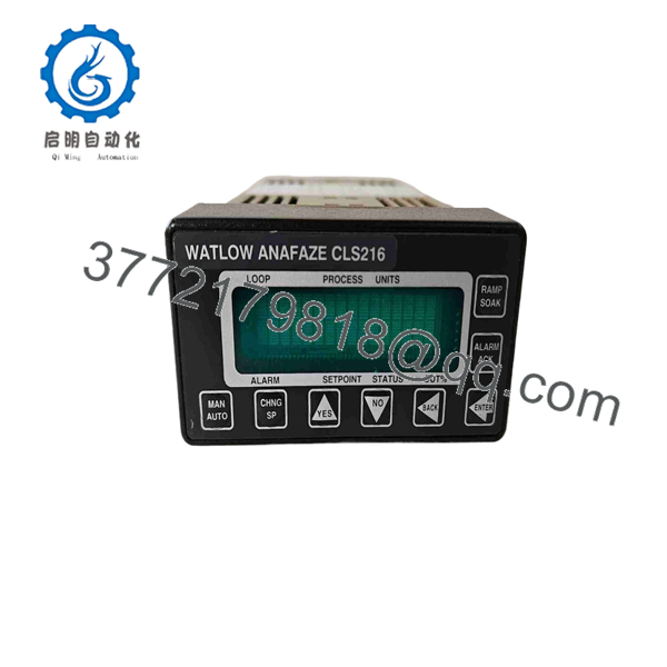
CLS216
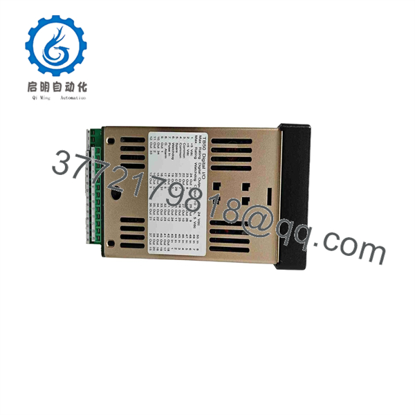
CLS216
Troubleshooting Quick Reference
| Symptom | Possible Cause | Relevance to This Part | Quick Check Method | Recommendation |
|---|---|---|---|---|
| Display is blank or controller will not boot | Missing supply voltage, blown fuse, failed transformer, loose terminal, failed controller power section | ✅ High | Measure supply voltage at the controller input terminals using a calibrated Fluke 115; compare measured supply to the exact nameplate and wiring diagram | Verify supply, fuse, neutral/common, and terminal torque before replacing CLS216. |
| One zone reads open sensor or overrange | Open thermocouple, broken RTD lead, loose terminal, wrong sensor type setting, damaged input channel | ✅ High | Disconnect power as required; check sensor continuity and resistance at the rear terminal; compare with a known-good sensor and verify the configured input type | Repair field wiring or correct configuration first. Replace the controller only if the fault follows the input channel. |
| All zones read incorrect temperatures | Wrong input configuration, common reference issue, incorrect thermocouple extension wire, failed supply/reference circuit, configuration corruption | ✅ Medium | Compare readings with a calibrated reference instrument; verify sensor types and polarity; check whether all affected zones share common wiring or a reference | Investigate configuration and common wiring before replacing the controller. |
| One heater zone stays on continuously | Welded output relay/SSR, output configured incorrectly, failed SSR, shorted control wiring, controller output fault | ✅ High | Place the loop in manual/off under approved procedure; measure the controller output state and voltage at the SSR or relay coil; isolate the output device | Check external SSR or relay first. Replace only if the output remains active with the controller output proven off. |
| One heater zone never turns on | Blown heater fuse, failed SSR/contactor, open heater, output disabled, alarm interlock active, output-channel fault | ✅ Medium | Check controller output indicator, measure control voltage at SSR input or relay coil, verify heater current with a clamp meter | Diagnose heater circuit and interlocks before replacing the controller. |
| Temperature oscillates or overshoots | Poor PID tuning, sensor location problem, oversized heater, failed cooling valve, mechanical process change | ❌ Low | Trend process value, setpoint, output percentage, and cycle time; compare tuning values with a stable zone | Run autotune or correct the process issue. Do not replace the controller based on poor tuning alone. |
| Controller communicates intermittently | Wrong RS-232/RS-485 settings, duplicate node address, bad cable, reversed RS-485 polarity, missing termination, ground-loop noise | ✅ Medium | Verify protocol, address, baud rate, parity, stop bits, RS-485 A/B polarity, shield, and termination against the host settings | Correct communication setup and cable issues before replacing . |
| Recipe or setup values disappear after a power cycle | Configuration not saved, memory fault, power interruption during write, incorrect job selection | ✅ High | Save the configuration, power-cycle under controlled conditions, then confirm setpoints and setup values; compare with the backup | Back up all parameters immediately. Replace or service the controller if it cannot retain verified settings. |
| Replacement controller powers up but controls the wrong zones | Terminal mismatch, incorrect model suffix, wrong output mapping, configuration not restored, firmware mismatch | ✅ High | Compare old and new labels, wiring terminal numbers, I/O maps, firmware version, and stored jobs before applying control power | Stop commissioning and restore the approved configuration. Do not transfer wiring by appearance alone. |
| Multiple zones show unusual readings after wiring work | Thermocouple polarity reversed, common wiring landed incorrectly, shield bonded improperly, incorrect sensor extension cable | ✅ Medium | Compare each terminal against the wiring drawing; verify thermocouple polarity and use the correct extension wire type | Correct field wiring before condemning the controller. |
❗ Firmware warning: units can have different firmware options and revisions. Record the startup display, firmware identifier, installed feature set, recipes, alarm setup, communication settings, and I/O configuration before removal. I have seen a replacement controller boot normally but fail acceptance because the original used a ramp/soak or enhanced function not available in the spare.
❗ Input-type warning: Thermocouple, RTD, voltage, current, and frequency inputs are not interchangeable settings. A Type K thermocouple configured as a Type J can look like a process failure. An RTD wired as a two-wire device when the system expects three-wire compensation can shift readings enough to ruin product quality.
❗ Terminal-block warning: Take detailed photos of every rear terminal before removal. Seriously. The most common mistake is assuming two multi-loop controllers have the same terminal layout because their front panels look identical. Verify terminal numbers and field wiring against the unit’s specific manual.
❗ Output warning: A controller output is often only the first stage of the heating or cooling circuit. A failed SSR, welded contactor, blown fuse, open heater, failed solenoid, or external safety interlock can mimic a failed . Prove the controller output state and the external final-control device separately.
❗ RS-485 warning: Do not land RS-485 wiring from memory. Confirm polarity, node address, baud rate, parity, termination, shield, and reference requirements. A reversed pair or duplicate address can create intermittent failures that look like a bad controller.
❗ Safety warning: Multi-zone thermal equipment can contain live mains voltage, hot surfaces, energized heaters, pressurized cooling circuits, and moving machine components. Apply lockout/tagout, verify absence of voltage, and confirm heaters cannot energize unexpectedly before replacing control hardware.
Keep these checks in mind and you will save yourself 90% of typical rework time. If you need assistance, provide technical support with complete nameplate photos, the full model suffix, firmware display, rear-terminal photos, I/O wiring diagram, sensor type, output-device details, alarm messages, communication settings, and configuration backup.
Frequently Asked Questions
What is the Watlow Anafaze ?
Watlow Anafaze is a multi-loop temperature and process controller in the CLS200 Compact Loop System family. It is commonly used for applications that need multiple independent PID-controlled thermal zones in one panel-mounted controller. The CLS200 product family supports sensor inputs including thermocouples, RTDs, linear voltage, current, and frequency.
How many control loops does support?
is the 16-loop version of the CLS200 family. Actual enabled inputs, outputs, and control features depend on the complete model code, installed firmware, terminal hardware, and system configuration. Do not assume every visible channel uses the same sensor or output type.
Can control both heating and cooling?
It can support heating and cooling functions where the exact hardware configuration and firmware provide the required outputs and control options. However, the base number does not define the installed output type. A unit may use relay, SSR/logic, analog, or other output arrangements based on its full ordering code.
Before purchase, confirm the required number of heat outputs, cooling outputs, alarm outputs, relay ratings, SSR drive type, analog-output requirements, and final-control devices.
Does support Modbus communication?
controllers include serial communications for computer interface and data acquisition. Available listings identify RS-232 and RS-485 communications with Modbus RTU or Anafaze protocol options, but actual protocol availability depends on the exact controller configuration and installed firmware.
Before replacement, record the existing communications settings: port used, protocol, node address, baud rate, parity, stop bits, RS-485 polarity, termination, and PLC/SCADA register map.
Can I hot-swap a Watlow ?
No. Treat this as a panel-mounted process controller replacement that requires controlled shutdown. Removing it can interrupt temperature measurement, release or de-energize heater commands, alter cooling commands, drop communications, and trigger alarms or safety shutdowns.
To be honest, live replacement is a bad plan on a multi-zone thermal machine. Isolate control power and heater power under the approved procedure, confirm every zone is safe, label all conductors, and verify no outputs can energize during the swap.
Will I lose setpoints, recipes, and PID tuning when replacing ?
A replacement unit may not contain your site’s setup. The old controller can hold loop setpoints, PID values, alarm limits, sensor types, output assignments, communication settings, recipe/job data, ramp/soak profiles, and special-control parameters.
Before removal, create a complete backup and record:
- Complete full model code and firmware version
- Each loop’s sensor type, range, calibration offset, and scaling
- Setpoints, PID values, cycle times, and output limits
- Heating/cooling action and control-output assignment
- Alarm limits, deviation alarms, and interlock behavior
- Recipe/job profiles and selection inputs
- RS-232/RS-485 protocol and serial communication settings
- Terminal wiring, shields, jumpers, output relays, SSRs, and external contactors
After replacement, validate one zone at a time in manual mode before allowing automatic operation.
Is obsolete, and why is New Surplus stock cheaper?
is a legacy controller family, so replacement inventory may come from New Surplus, refurbished, or used-tested sources. New Surplus hardware typically comes from unused project stock, cancelled machine builds, distributor inventory, warehouse spares, or equipment upgrades. The lower price often reflects secondary-market sourcing and product age rather than an automatic defect.
For a New Original / New Surplus unit, request:
- Actual nameplate, front-panel, rear-terminal, and packaging photos
- Complete ordering code, not only
- Firmware version and boot-screen photo
- Input/output configuration and terminal-board confirmation
- Condition statement: Factory Sealed, New Original / New Surplus, or Refurbished (tested)
- Warranty duration, return terms, actual available quantity, and dispatch lead time
What test process should a supplier complete before shipment?
A proper supplier test process should be traceable and specific to the complete variant:
- Inbound inspection and traceability: Verify OEM label, complete ordering code, firmware marking, source documents, serial number where present, and packing information. Inspect the display, membrane keypad, housing, mounting hardware, terminals, connector blocks, and labels for scratches, corrosion, cracks, heat damage, UV yellowing, rework marks, or missing components.
- Power-on test: Apply the exact rated supply shown on the nameplate through a protected test fixture. Confirm normal boot behavior, readable display, keypad response, absence of internal fault messages, and stable current draw.
- Input simulation test: Use calibrated thermocouple, RTD, voltage, current, and frequency simulators as supported by the exact configuration. Test each available input at low, midscale, and high values, then verify indicated values, sensor-fault detection, and alarm response.
- Output test: Test each relay, SSR/logic, analog, or digital output with a protected load fixture. Confirm output action, manual control, PID demand response, alarm behavior, and output de-energization under simulated fault conditions.
- Communications test: Connect through the configured RS-232 or RS-485 port. Verify correct protocol, node address, baud rate, parity, data exchange, and stable operation using a known-good Modbus or Anafaze host test system.
- Configuration-retention test: Save a non-production test configuration, power-cycle the controller, and confirm it retains settings. Document any firmware-specific behavior and disclose whether buyer configuration is unknown or cleared.
- Load and thermal test: Operate the controller with representative input/output activity for more than 24 hours where the test bench permits. Monitor display stability, communications, input drift, output behavior, and enclosure temperature.
- Final QC and packaging: Require inspector sign-off, terminal protection, anti-static handling where appropriate, bubble wrap, heavy-duty corrugated packaging, and a dated QC-passed label. Test photos, a firmware record, I/O test results, and the test report should be available upon request.



