
 WhatsApp: +86 16626708626
 Email:
  Phone: +86 16626708626
Description
Key Technical Specifications
| Parameter | Specification |
|---|---|
| Manufacturer | Watlow Anafaze |
| Model | CLS204 |
| Series | CLS200 |
| Product Type | Multi-loop PID temperature/process controller |
| Number of Loops | 4 |
| Analog Input Configuration | 4 differential |
| Thermocouple Types | B, E, J, K, R, S, T |
| RTD Input | 100 Ω platinum, 2- or 3-wire |
| Linear Inputs | 0–20 mA, 4–20 mA, 0–100 mV, 0–500 mV, 0–1 V, 0–5 V, 0–10 V; configuration-dependent |
| Input Sampling Rate | 6 samples/s per channel |
| Update Time | 0.167 s |
| Measurement Resolution | 0.006%, greater than 14 bits |
| Noise Rejection | 120 dB at 60 Hz |
| Temperature Coefficient | 40 ppm/°C |
| Digital Inputs | TTL-level inputs; configuration-dependent |
| Digital Outputs | Up to 34 with 50-pin terminal board |
| Control Outputs | Up to 2 user-assigned outputs per loop |
| Serial Interface | EIA/TIA-232 or EIA/TIA-485 |
| Baud Rates | 2,400 / 9,600 / 19,200 baud |
| Communication Protocols | Modbus RTU; ANSI X3.28-1976-compatible |
| Display | 32-character vacuum fluorescent display |
| Keypad | 8 keys |
| Power Supply Option | 120/240 VAC, 50/60 Hz adapter; configuration-dependent |
| Auxiliary DC Supply | 15 VDC class supply for specified power-adapter configuration |
Watlow’s official CLS200 documentation identifies the input types, scan rate, resolution, digital I/O options, serial interfaces, baud rates, and configurable power-supply options.
Ordering-Code Warning
CLS204 is the base model designation, not necessarily a complete ordering number. Watlow’s ordering structure adds fields for controller type, terminal board, power supply, SCSI cable, serial cable, serial jumper configuration, and special/custom options.
For procurement, therefore, a unit marked only CLS204 should be checked against the original nameplate and configuration before being treated as an exact replacement.
Product Introduction
The Watlow Anafaze CLS204 is a four-loop member of the CLS200 multi-loop controller family. It provides four differential analog inputs for temperature and process measurements and executes independent control loops for applications such as thermal processing and machine heating. Watlow specifies thermocouple and RTD support along with configurable linear voltage/current inputs.
The controller also provides serial communications through EIA/TIA-232 or EIA/TIA-485, with Modbus RTU and an ANSI X3.28-1976-compatible protocol available. The exact I/O and power arrangement depends on the complete CLS200 ordering code rather than the CLS204 base designation alone.
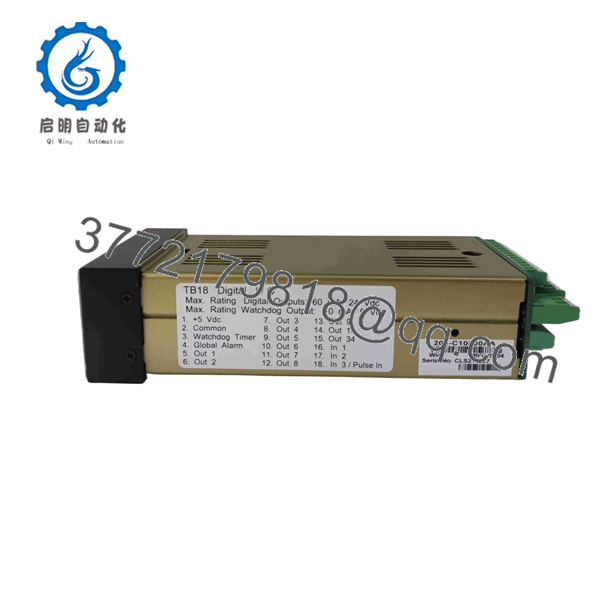
CLS204
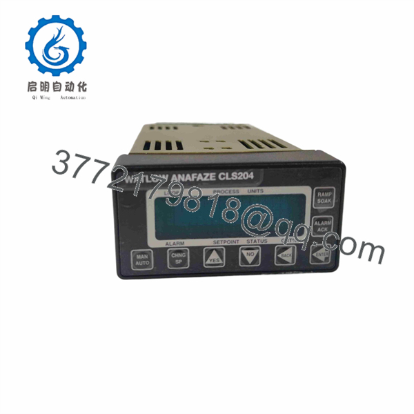
CLS204
Installation & Configuration Guide
Stage 1 — Pre-Installation Preparation
Approximate time: 20–30 minutes
- Follow the plant’s lockout/tagout procedure and isolate hazardous energy.
- Record the complete controller label, including the CLS204 base model and all configuration-code characters.
- Photograph the front panel, rear connections, terminal board, and serial connections.
- Back up the controller configuration, recipes/jobs, PID settings, alarm limits, and communication parameters.
- Record each of the four loop assignments and connected sensor types.
- Identify whether the system uses the 18-pin or 50-pin terminal-board arrangement.
- Confirm the controller’s serial interface setting: RS-232 or RS-485.
- Verify the replacement power-supply configuration.
⚠️ Do not order a generic solely from the four-loop designation if the existing unit has custom inputs, firmware, terminal-board, or communications options.
Stage 2 — Removing the Existing Controller
Approximate time: 15–25 minutes
- Place the process in the approved maintenance state.
- Isolate controller power.
- Label all sensor, control-output, digital-I/O, and communication wiring.
- Photograph terminal positions before disconnecting the cables.
- Disconnect the serial communication cable if installed.
- Disconnect the SCSI/terminal-board interface.
- Remove the controller from its mounting arrangement.
- Inspect connectors, terminal boards, and cables for corrosion, loose contacts, or physical damage.
Stage 3 — Installing
Approximate time: 20–30 minutes
- Confirm the replacement is the correct configuration.
- Install the controller using the existing mounting arrangement.
- Reconnect the terminal-board/SCSI connection.
- Restore sensor wiring to the original channels.
- Confirm thermocouple polarity and RTD lead configuration.
- Reconnect control outputs according to the recorded loop assignments.
- Reconnect RS-232 or RS-485 communication wiring as applicable.
- Restore the documented communication jumper configuration.
- Do not change sensor types or scaling parameters simply because the replacement controller powers up normally.
- Verify all connections before applying power.
Stage 4 — Power-On & Testing
Approximate time: 30–60 minutes
- Perform a complete wiring inspection.
- Apply power using the original system voltage arrangement.
- Verify the display and keypad initialize correctly.
- Confirm all four channels report valid process measurements.
- Check sensor type and input scaling for each loop.
- Restore PID parameters, setpoints, alarm limits, and recipe/job data.
- Verify RS-232/RS-485 communication with the host system or PLC.
- Test representative temperature inputs against a calibrated simulator where available.
- Verify control outputs at a controlled test condition.
- Confirm alarm and interlock behavior before returning the process to automatic control.
- Save the verified configuration as the new maintenance backup.
⚠️ If a loop displays an implausible temperature immediately after replacement, check the sensor type, polarity, RTD wiring, scaling, and input configuration before changing PID parameters.
FAQ
What is the Watlow Anafaze ?
The is a four-channel CLS200 multi-loop temperature/process controller. Watlow documentation specifies four differential analog inputs and a six-samples-per-second scan rate for this model.
How many control loops does have?
The provides four independent control loops. The related CLS208 and CLS216 models provide eight and 16 channels, respectively.
What sensors can accept?
Depending on the configuration, the supports thermocouples including B, E, J, K, R, S, and T, plus 100 Ω platinum RTDs and configurable linear voltage/current inputs.
Does support Modbus?
Yes. Watlow’s CLS200 specification identifies Modbus RTU and an ANSI X3.28-1976-compatible protocol, with EIA/TIA-232 or EIA/TIA-485 serial communications.
What is the sampling rate of ?
The specified input sampling rate is 6 samples per second per channel, corresponding to an update time of approximately 0.167 s.
Does have built-in analog outputs?
The base architecture does not provide a universal built-in analog-output channel. Watlow’s documentation describes optional DAC/SDAC modules for analog-output requirements.
Is a complete ordering number?
Not necessarily. identifies the four-channel controller configuration, while additional ordering-code characters specify controller type, terminal board, power supply, cables, serial jumper configuration, and custom options.
For an exact replacement, compare the complete original ordering code, terminal-board arrangement, firmware/custom options, sensor configuration, and communication settings rather than matching only the base model.



