
 WhatsApp: +86 16626708626
 Email:
  Phone: +86 16626708626
Description
Key Technical Specifications
| Parameter | Value |
|---|---|
| Manufacturer | Wavecrest |
| Model | DTS-2079 |
| Product Type | Digital time interval analyzer and jitter measurement instrument |
| Primary Function | Characterizes timing, jitter, period, pulse width, and clock behavior |
| Intended Use | R&D, production test, communications, semiconductor, digital-system, and timing-analysis work |
| Input Channels | Two independent channels reported |
| Input Frequency Range | DC to 3 GHz reported |
| Maximum Data Rate | Verify from official DTS-2079 specification table before application use |
| Input Impedance | 50 Ω reported |
| Input Connector Type | SMA coaxial input connectors reported |
| Trigger-Level Range | −2 V to +2 V adjustable, reported |
| Time Resolution | Sub-picosecond reported |
| Timing Measurement Range | Nanoseconds to seconds reported |
| Jitter Measurements | Clock jitter and related timing-parameter analysis |
| Pulse Measurements | Pulse width, period, rise time, and fall time reported |
| Statistical Functions | Histogram and statistical analysis reported |
| External Reference | External reference-clock input reported |
| Remote Interfaces | GPIB, RS-232, and USB reported; verify actual installed instrument |
| Internal Display / Controls | Front-panel display and operator controls reported |
| AC Input Supply | 100–240 V AC, 50/60 Hz reported |
| Operating Temperature | 0 to +45 °C reported |
| Warm-Up Recommendation | 30 minutes reported before precision measurement |
| Calibration Status | Must be checked from the calibration label and certificate for the exact instrument |
| Lifecycle Status | Legacy laboratory instrument; confirm current OEM service, calibration, and software support before purchase |
Wavecrest identifies the DTS-2079 as an instrument for design and characterization engineers to analyze jitter and critical timing parameters of high-frequency clocks. An available original Wavecrest page lists core categories including frequency range, maximum data rate, minimum pulse width, jitter noise floor, jitter measurement accuracy, hardware resolution, time-base accuracy, and time-base stability.
Several aftermarket descriptions provide more detailed values, including two channels, DC to 3 GHz input range, 50 Ω inputs, adjustable −2 V to +2 V triggers, GPIB/RS-232/USB interfaces, and 100–240 V AC supply. Treat these values as provisional until confirmed against an original DTS-2079 manual, instrument rear-panel label, and calibration record.
Product Introduction
The Wavecrest DTS-2079 is a digital time interval analyzer designed to measure jitter and timing behavior in high-frequency clock, pulse, and serial-data signals. It supports design verification and production testing where timing margins matter, including semiconductor evaluation, telecommunications equipment, high-speed digital circuits, optical modules, aerospace electronics, and precision instrument calibration.
The DTS-2079 is a laboratory timing instrument, not a PLC, data-acquisition module, servo drive, or general industrial controller. Online marketplace descriptions assign it conflicting functions, but Wavecrest’s product reference identifies it as a jitter and high-frequency clock timing analyzer. Verify the installed options, channel connectors, trigger range, firmware, software, and calibration status before purchase.
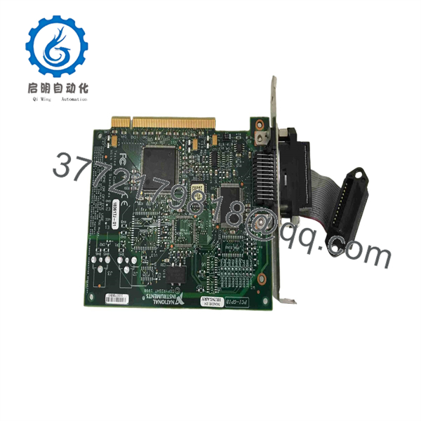
DTS-2079
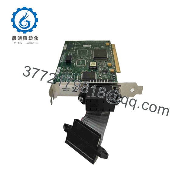
DTS-2079
Troubleshooting Quick Reference
| Symptom | Possible Cause | Relevance to This Part | Quick Check Method | Recommendation |
|---|---|---|---|---|
| Instrument will not power on | AC source absent, blown input fuse, damaged power cord, failed internal supply, front-panel power switch issue | ✅ High | Verify AC voltage at the wall outlet and instrument inlet using an approved meter. Inspect the power cord, fuse holder, and rear-panel voltage markings. | Check external AC power and fuse rating before replacing or servicing the instrument. Do not install an arbitrary fuse value. |
| Display powers up but no input signal is detected | Wrong input connector, bad SMA cable, signal below trigger threshold, wrong trigger level, incorrect termination, failed input channel | ✅ High | Connect a known-good signal source through a verified 50 Ω SMA cable. Set the correct trigger level and confirm the source amplitude at the instrument input. | Verify source amplitude, 50 Ω loading, and trigger setting before diagnosing a channel fault. |
| Jitter result is much higher than expected | Noisy source, improper impedance match, poor SMA connection, cable movement, ground noise, incorrect bandwidth or measurement setup | ❌ Usually low | Replace the input cable, secure all SMA connectors, verify 50 Ω source impedance, and compare the result with a calibrated low-jitter reference. | Troubleshoot signal integrity and measurement setup first. The instrument often exposes source or cabling noise rather than creating it. |
| Measurements vary between runs | Insufficient warm-up, unstable reference clock, noisy signal source, trigger setting too close to noise, temperature changes | ⚠️ Medium | Allow at least 30 minutes of warm-up, use a stable reference, and repeat measurement with unchanged cables and settings. Review time-base and reference status. | Stabilize the setup before declaring the defective. Precision timing tests are sensitive to temperature and connection changes. |
| One channel works but the other does not | Damaged SMA connector, failed input stage, channel-specific trigger setting, cable issue | ✅ Medium | Swap the same known-good source and cable between Channel 1 and Channel 2 without changing settings. Inspect SMA center pins and threads. | If failure follows one channel with the same source and cable, send the instrument for qualified repair or replacement evaluation. |
| Trigger is unstable or false-triggering | Trigger level set incorrectly, input amplitude too low, overshoot/ringing, damaged cable, source noise | ⚠️ Medium | Observe the waveform with a suitable oscilloscope, then set trigger level near the valid signal threshold rather than in the noise region. | Improve source signal integrity and set a stable trigger threshold. Do not use an unspecified input amplitude. |
| Remote computer cannot communicate | Wrong GPIB address, RS-232 baud mismatch, USB driver issue, bad cable, incompatible software | ⚠️ Medium | Verify the physical interface selected, instrument address, port settings, cable type, and computer driver. Test communications with the simplest supported command utility. | Match the host configuration to the actual fitted interface. Do not assume every includes all reported interfaces. |
| External reference does not lock | Incorrect reference frequency, low reference amplitude, bad cable, wrong reference configuration, failed input | ⚠️ Medium | Check reference frequency and amplitude against instrument requirements. Test with a known-good reference source and short 50 Ω cable. | Verify the exact reference-input specification in the manual before replacement. |
| Input channel reads zero or clips | Signal amplitude outside allowed range, DC offset issue, damaged input protection, wrong coupling/termination | ✅ Medium | Measure source level with a calibrated instrument before connecting. Confirm attenuation and termination. Inspect for a bent SMA center contact. | Protect the input with a suitable attenuator if required. Do not exceed the specified input limit. |
| Instrument fails self-test or calibration verification | Internal timing reference drift, failed channel electronics, firmware issue, aged components | ✅ High | Record all self-test messages, serial number, firmware version, calibration due date, and measurement results against a traceable reference. | Do not use it for acceptance testing until it passes calibration or is repaired by a qualified metrology service. |
| Replacement unit powers up but produces different results | Different option set, calibration expired, firmware difference, reference source mismatch, setup not replicated | ⚠️ Medium | Compare software/firmware versions, installed options, calibration certificates, input setup, trigger level, reference source, and environmental conditions. | Treat measurement correlation as a calibration task, not a quick swap. Verify against traceable standards before release to production. |
❗ Input-protection warning: Do not connect unknown signals directly to a 50 Ω high-frequency input. Check amplitude, DC offset, repetition rate, and source impedance first. Use properly rated SMA attenuators, DC blocks, or signal-conditioning equipment when the signal could exceed the instrument’s permitted input range.
❗ Calibration warning: A working display and plausible measurement result do not prove accuracy. For jitter, timing-margin, and acceptance-test work, verify the calibration certificate, calibration due date, time-base specification, and channel performance. Let the instrument warm up for the documented stabilization period before making precision measurements.
If troubleshooting remains unresolved, provide technical support with serial-number and rear-panel photos, startup or self-test messages, firmware version, calibration label, input-signal frequency and amplitude, trigger settings, cable and attenuator details, reference-clock settings, and captured measurement results.
Frequently Asked Questions
What is the Wavecrest ?
The Wavecrest is a digital time interval analyzer used to measure jitter and other critical timing parameters of high-frequency clocks and digital signals. It is aimed at design, characterization, and test engineers rather than PLC or process-control users.
Is a PLC, servo drive, or industrial data-acquisition module?
No. Although some generic marketplace listings misclassify it, the original Wavecrest description identifies as a timing and jitter analysis instrument for high-frequency clocks. It should be treated as electronic test equipment.
What signals can measure?
The available original product page identifies high-frequency clocks and timing parameters as the primary target. Aftermarket descriptions report measurement of time intervals, jitter, period, pulse width, rise time, fall time, and serial or clock signals. Confirm exact supported signal types, amplitude limits, and trigger requirements from the official manual for the supplied instrument.
Does have two input channels?
Several aftermarket sources describe two independent channels. However, verify the actual front-panel connector layout, option configuration, and manual for the exact instrument before writing a test method or procurement specification.
What input frequency range does support?
An aftermarket source reports DC to 3 GHz. The original Wavecrest page confirms that frequency range is an important specification category but does not expose the full numeric table in the available search result. Confirm the range, maximum data rate, and minimum pulse width from the original manual or data sheet before connecting high-speed signals.
Does require 50 Ω input signals?
An aftermarket description reports 50 Ω input impedance. In practical high-speed measurement work, use properly matched 50 Ω sources, SMA cables, attenuators, and terminations unless the official manual for your exact configuration specifies otherwise. Mismatch reflections can materially distort jitter measurements.
Can I hot-swap input cables while is powered?
Do not treat it as hot-swappable in the industrial-control sense. You may connect or disconnect properly conditioned low-energy test signals only when it is safe for the test setup and within the instrument’s input ratings. Never connect live unknown, high-voltage, high-power, or charged signals to the input. Power down the source or isolate it before changing a test connection when there is any doubt.
Will I need software to use ?
Front-panel measurement functions may be available, while remote automation can require software or command access through the instrument’s installed communications interface. Listings mention GPIB, RS-232, and USB, but the exact interface set and compatible software must be verified from the physical unit.
Why is a New Surplus cheaper than a current timing analyzer?
New Surplus units can come from closed labs, canceled test programs, telecom inventory, semiconductor test lines, or distributor overstock. The price often reflects product age, calibration uncertainty, obsolete software, missing accessories, or limited repair support. Ask for exact-unit photos, serial number, calibration certificate, self-test results, installed interface options, included cables or adapters, warranty terms, and return conditions.
What testing should a supplier perform before shipping a refurbished ?
Request cosmetic and connector inspection; verified power-up; display and keypad test; self-test results; both-channel test using a calibrated timing source; frequency and trigger-response check; reference-clock test if equipped; remote-interface communication check; a warm-up and stability run; and calibration verification against traceable standards. For timing instruments, a functional test is not equivalent to a current calibration certificate.



