
 WhatsApp: +86 16626708626
 Email:
  Phone: +86 16626708626
Description
3. Key Technical Specifications
| Parameter | Value |
|---|---|
| Manufacturer | Woodward |
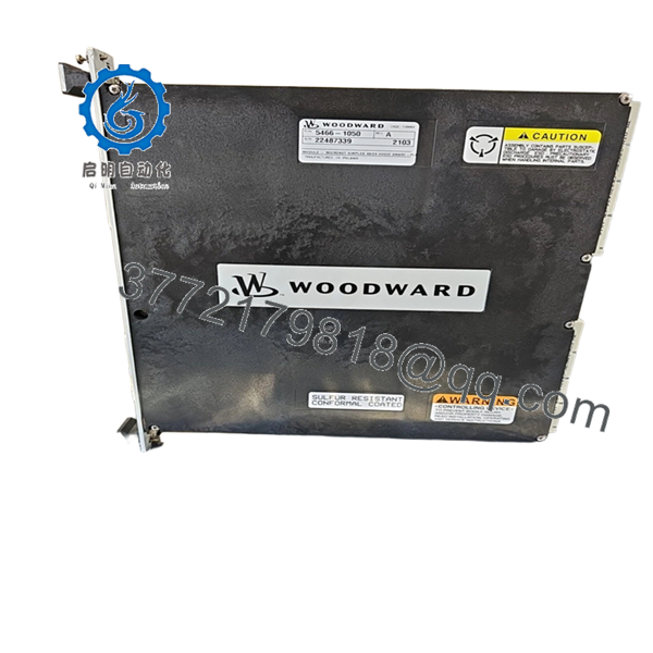
| Model Number | 5466-1050 |
| Product Type | High-Density Discrete Input/Output Module |
| Platform | MicroNet / MicroNet Plus |
| Module Architecture | HDDIO Smart-Plus |
| Input Capacity | 48 Discrete Inputs |
| Output Capacity | 24 Discrete Outputs |
| Field Voltage | 24 VDC Nominal |
| Input OFF Threshold | < 8 VDC at 1.5 mA |
| Isolation | 500 VDC to Earth Ground |
| Isolation | 1000 VDC to Control Common / Channel Isolation |
| Supported Controllers | CPU5200, P1020 |
| Chassis Compatibility | Full-Size or Narrow Chassis |
| Storage Temperature | -40 °C to +105 °C |
| Configuration | Simplex, Redundant Architecture Support |
| Field Connection | FTM via High-Density Cables |
| Weight | Approximately 2.16 kg |
| Dimensions | 22.2 cm × 8.0 cm × 26.6 cm |
The 5466-1050 is identified as a MicroNet Simplex 48/24 HDDIO Smart-Plus module providing 48 discrete inputs and 24 discrete outputs. It supports existing MicroNet Field Termination Modules (FTMs) and is commonly used with CPU5200 and P1020 controller platforms.
4. Product Introduction
The WOODWARD 5466-1050 is a high-density discrete input/output module designed for Woodward MicroNet and MicroNet Plus control systems. The module provides 48 discrete inputs and 24 discrete outputs for turbine control, compressor control, engine management, and critical industrial automation applications.
In field upgrades, the 5466-1050 is frequently used as a replacement for older HDD discrete I/O modules because it maintains compatibility with existing MicroNet FTMs and cabinet layouts. In many installations, this allows modernization of I/O hardware without rewiring the field termination assemblies.
- 5466-1050
- 5466-1050
5. Installation & Configuration Guide
Stage 1: Pre-Installation Preparation (10–15 Minutes)
⚠️ Safety First
- Notify operations personnel of planned downtime.
- Place the turbine, compressor, or process in a verified safe state.
- Apply lockout/tagout procedures.
- Remove all control power.
- Wait at least 5 minutes for capacitor discharge.
Tools Required
- ESD wrist strap
- ESD mat
- PH1 screwdriver
- Fluke 115 multimeter
- Wire labels
- Smartphone camera
- Flashlight
Data Backup
- Archive current controller logic.
- Save MicroNet configuration files.
- Record network addresses.
- Photograph:
- Existing module label
- Wiring connections
- DIP switch settings
- FTM connections
- Cabinet layout
❗I’ve seen shutdowns extended by hours because someone assumed the cabinet drawings were current. Take photos before touching anything.
Stage 2: Removing the Old Module (5–10 Minutes)
- Open cabinet access panels.
- Locate the 5466-1050 module.
- Label all cables and terminal assemblies.
- Disconnect FTM cables carefully.
- Release module retaining hardware.
- Pull the card straight out of the chassis guides.
⚠️ Do not twist the module during removal.
MicroNet backplane connectors are expensive and difficult to replace during an outage.
- Inspect:
- Backplane connectors
- Card guides
- Dust accumulation
- Signs of overheating
⚠️ Retain the original module until commissioning is complete.
Stage 3: Installing the New Module (10 Minutes)
- Wear a grounded ESD wrist strap.
- Verify:
- Part Number = 5466-1050
- Correct hardware revision
- No shipping damage
Configuration Clone (Crucial)
- Compare all DIP switches.
- Match jumper settings exactly.
- Verify field voltage configuration.
- Verify FTM type.
❗This is the most common rookie mistake, but it happens constantly. Take a picture before you pull it. I can’t stress this enough.
- Slide the replacement module into the chassis.
- Ensure the module seats fully.
- Tighten retaining hardware.
- Reconnect FTM cables.
Self-Checklist
- Part number verified
- DIP settings match
- Jumpers match
- FTM cables connected
- Module fully seated
- Retention hardware secure
Stage 4: Power-On & Testing (15 Minutes)
Pre-Power Check
- Verify control power voltage.
- Check for shorts on the 24 VDC rail.
- Verify cabinet grounding continuity.
Power-Up Procedure
- Energize the rack only.
- Observe startup LEDs.
- Verify module communication.
- Connect engineering workstation.
- Confirm:
- Module recognized
- No communication faults
- Correct configuration detected
- Proper I/O status
- Test discrete inputs.
- Test discrete outputs.
- Verify field devices respond correctly.
⚠️ Troubleshooting Note
- Fault LEDs often indicate firmware or configuration mismatches.
- Missing I/O points usually trace back to incorrect FTM configuration.
- Communication faults frequently result from improperly seated modules.
Quality Control & Functional Verification SOP
1. Inbound Inspection & Traceability
Each 5466-1050 module undergoes:
- OEM identification verification.
- Serial number documentation.
- Anti-counterfeit inspection.
- Visual examination under magnification.
Inspection criteria:
- No corrosion
- No scratched PCB traces
- No rework marks
- No UV yellowing
- No damaged connectors
Accessory audit includes:
- Original labels
- Factory packaging when available
- Certificates and documentation
2. Live Functional Testing
Testing is performed on a genuine MicroNet-compatible test rack.
Procedures include:
- Power-on self-test.
- LED verification.
- Backplane communication testing.
- Full discrete input simulation.
- Full discrete output testing.
- 24-hour continuous operation.
- Thermal monitoring under load.
A test report is generated for each tested unit.
Test videos and photos are available upon request.
3. Electrical Parameter Testing
Testing includes:
- 500 V Megger insulation resistance test
- Ground continuity verification
- Supply rail measurements
- Hipot testing where applicable
Acceptance criteria:
- Greater than 10 MΩ insulation resistance
4. Firmware & Configuration Verification
- Firmware revision documented.
- Hardware revision recorded.
- DIP switch settings photographed.
- Configuration archived.
5. Final QC & Packaging
- QC sign-off.
- ESD-safe packaging.
- Anti-static bag sealing.
- Bubble-wrap protection.
- Heavy-duty export carton.
- QC Passed label applied with inspection date.
Common Replacement Pitfalls From Field Experience
❗ Firmware Revision Mismatch
A newer HDDIO Smart-Plus module may physically fit but still generate communication issues.
I’ve seen maintenance teams spend two days troubleshooting a perfectly good module because the controller firmware didn’t support the installed Smart-Plus revision.
Avoidance:
- Record current firmware before removal.
- Verify Coder software version.
- Request firmware verification before shipment.
❗ DIP Switch and Configuration Errors
This causes more startup failures than defective hardware.
One incorrect address or voltage selection can disable an entire I/O segment.
Avoidance:
- Photograph everything.
- Verify switch settings twice.
- Compare with site documentation.
❗ FTM and Cable Configuration Mistakes
The 5466-1050 supports multiple FTM arrangements.
I’ve seen technicians connect the wrong FTM configuration and spend hours troubleshooting missing channels.
Avoidance:
- Verify FTM type before installation.
- Confirm cable routing.
- Check channel allocation against drawings.
❗ Power Supply Capacity
The module can operate with redundant or single power supplies, but overall cabinet loading still matters.
Avoidance:
- Measure voltage under load.
- Maintain at least 20% spare power capacity.
- Verify supply health before startup.
❗ Electrostatic Discharge (ESD)
I once watched a contractor remove a Smart-Plus card during winter without grounding himself. The module never came back online.
Avoidance:
- Use a grounded wrist strap.
- Work on an ESD mat.
- Store modules in anti-static packaging.
Keep these checks in mind and you’ll save yourself 90% of typical rework time.
6. Frequently Asked Questions (FAQ)
Q1: Can I hot-swap the WOODWARD 5466-1050?
Under certain MicroNet architectures, Woodward documentation and field experience indicate the module can be replaced while the controller remains online. However, site procedures, redundancy architecture, and risk tolerance vary significantly. For critical turbine applications, I generally recommend a controlled shutdown unless the operating philosophy explicitly permits online replacement.
Q2: Is the 5466-1050 obsolete?
The 5466-1050 remains part of the MicroNet Smart-Plus family, but many installed systems are now considered legacy control platforms. Availability increasingly depends on surplus inventory, strategic spare stock, and tested refurbished inventory.
Q3: What discrete I/O capacity does this module provide?
The module provides:
- 48 discrete inputs
- 24 discrete outputs
This high channel density allows significant cabinet space savings compared to multiple lower-density I/O cards.
Q4: Is the 5466-1050 compatible with CPU5200 systems?
Yes.
The module is commonly deployed with CPU5200-based MicroNet systems and supports Smart-Plus architecture features including enhanced diagnostics and self-monitoring functions. Verify your installed Coder version before deployment.
Q5: Will I lose my application logic when replacing this module?
No.
The 5466-1050 is an I/O module. Application logic resides in the controller CPU rather than the HDDIO module itself.
Even so, always perform a complete backup before maintenance.
Q6: Why is surplus inventory often less expensive than OEM procurement?
Because surplus inventory typically originates from:
- Plant spare-part inventories
- Project cancellations
- Distributor excess stock
- Facility modernization projects
The hardware may be unused but usually does not include OEM engineering support services.
Q7: What information should I provide before requesting a quote?
Send:
- Module nameplate photo
- Controller model (CPU5200, P1020, etc.)
- Firmware revision
- Chassis photo
- FTM configuration details
- Existing I/O architecture (Simplex, Redundant, or TMR)
That information eliminates most compatibility issues before shipment and helps avoid emergency downtime.


