
 WhatsApp: +86 16626708626
 Email:
  Phone: +86 16626708626
Description
3. Key Technical Specifications
| Parameter | Value |
|---|---|
| Manufacturer | Woodward |
| System Model | 8262-1040 Rev D |
| Product Family | 505DE Digital Governor System |
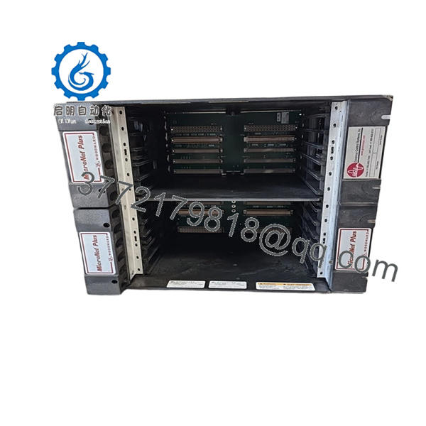
| Control Platform | MicroNet Plus |
| Chassis | 5453-829 Redundant 8-Slot Chassis |
| CPU Modules | 2 × 5466-1035 CPU5200 Processors |
| Processor Type | PowerPC-5200, 400 MHz |
| Flash Memory | 64 MB per CPU |
| RAM | 128 MB per CPU |
| Power Supply Configuration | Dual Redundant Power Supplies |
| Discrete I/O | 2 × 5466-1158 HDDIO Smart-Plus Modules |
| Analog I/O | 3 × 5466-316 Analog Combo Modules |
| Architecture | Redundant Control Platform |
| Application | Double Extraction Steam Turbine Control |
| Communications | Ethernet, Modbus, Woodward GAP |
| Chassis Cooling | Smart Fan Redundant Cooling System |
The 8262-1040 package was supplied by Woodward as a complete 505DE Double Extraction Turbine Control System built around the 5453-829 MicroNet Plus 8-Slot Redundant Chassis. Standard configurations included dual CPU5200 processors, redundant power supplies, analog I/O modules, and HDDIO Smart-Plus modules.
4. Product Introduction
The WOODWARD 8262-1040 Rev D is a pre-engineered 505DE turbine control package designed for double-extraction steam turbine applications. The system uses the MicroNet Plus platform and integrates redundant CPUs, analog control modules, discrete I/O, and communications infrastructure into a single governor and process control solution.
A major advantage of the 8262-1040 architecture is that it provides turbine speed control, extraction pressure regulation, load management, and protection functions within a redundant control environment. In operating plants, engineers often retain these systems because migration to a newer platform typically requires control logic validation, turbine retuning, and shutdown planning that can far exceed the cost of maintaining existing hardware.

- 8262-1040 Rev D
5. Installation & Configuration Guide
Stage 1: Pre-Installation Preparation (15 Minutes)
⚠️ Safety First
- Notify plant operations of the scheduled outage.
- Verify turbine shutdown and lockout conditions.
- Apply lockout/tagout procedures.
- Isolate control cabinet power.
- Wait at least 5 minutes for capacitor discharge.
Tools Required
- ESD wrist strap
- ESD mat
- PH1 screwdriver
- Fluke 115 multimeter
- Wire labels
- Smartphone camera
- Flashlight
Data Backup
- Upload the complete 505DE application.
- Backup all GAP configuration files.
- Record network addresses.
- Photograph:
- CPU modules
- Chassis layout
- FTM connections
- Power supply wiring
- Ethernet connections
- DIP switch settings
❗For 505DE systems, application backups are mandatory. Unlike a simple I/O card replacement, a governor system can require complete restoration of turbine control logic.
Stage 2: Removing the Old Hardware (10–20 Minutes)
- Open the cabinet.
- Verify the target chassis is de-energized.
- Label all field cables.
- Disconnect communication cables.
- Remove power supply connections.
- Release module retention hardware.
- Remove modules individually.
⚠️ Do not remove multiple modules simultaneously unless cabinet documentation is exceptionally clear.
- Inspect:
- Backplane connectors
- Fan assemblies
- Power supply connectors
- Grounding points
⚠️ Keep all removed hardware available until commissioning is complete.
Stage 3: Installing the Replacement System (20 Minutes)
- Wear ESD protection.
- Verify:
- 8262-1040 kit contents
- 5453-829 chassis revision
- CPU model numbers
- Power supply ratings
Configuration Clone (Crucial)
- Restore all configuration settings.
- Verify CPU redundancy settings.
- Verify network parameters.
- Verify Modbus communication mapping.
- Verify extraction pressure control settings.
❗This is the most common rookie mistake, but it happens constantly. Take a picture before you pull it. I can’t stress this enough.
- Install chassis.
- Install CPUs.
- Install I/O modules.
- Reconnect all field wiring.
Self-Checklist
- Chassis secured
- CPUs installed
- Power supplies installed
- I/O modules seated
- Ethernet connected
- Grounding verified
- Configuration restored
Stage 4: Power-On & Testing (20–30 Minutes)
Pre-Power Check
- Verify cabinet grounding.
- Verify power supply voltages.
- Check for shorts.
Power-Up Procedure
- Energize power supplies.
- Observe chassis fan operation.
- Verify CPU startup sequence.
- Connect engineering workstation.
- Verify:
- CPU redundancy healthy
- Communications active
- I/O modules recognized
- Application loaded
- Verify turbine speed feedback.
- Verify extraction pressure control loops.
- Perform dry-run testing before returning the machine to service.
⚠️ Troubleshooting Note
- CPU fault LEDs often indicate firmware incompatibility.
- Communication alarms usually originate from IP configuration errors.
- Extraction control faults frequently trace back to incorrect analog scaling.
Quality Control & Functional Verification SOP
1. Inbound Inspection & Traceability
Each 8262-1040 system undergoes:
- OEM part verification.
- Serial number documentation.
- Anti-counterfeit inspection.
- Visual inspection.
Verification includes:
- No corrosion
- No damaged connectors
- No PCB repair marks
- No fan damage
- No cabinet contamination
2. Live Functional Testing
Testing is performed on a genuine MicroNet Plus test platform.
Procedures include:
- Power-on self-test.
- CPU boot verification.
- Redundancy testing.
- Ethernet communication testing.
- Analog I/O simulation.
- Discrete I/O simulation.
- Continuous operation exceeding 24 hours.
A formal test report is generated.
Test photos and videos are available upon request.
3. Electrical Parameter Testing
Testing includes:
- 500 V Megger insulation testing
- Ground continuity testing
- Power rail validation
- Hipot testing where applicable
Acceptance target:
- Greater than 10 MΩ insulation resistance
4. Firmware & Configuration Verification
- CPU firmware versions recorded.
- Hardware revisions documented.
- Configuration backups archived.
- DIP switch settings photographed.
5. Final QC & Packaging
- QC sign-off.
- Anti-static packaging.
- ESD bagging.
- Protective foam packaging.
- Heavy-duty export carton.
- QC Passed label with date.
Common Replacement Pitfalls From Field Experience
❗ Firmware Revision Mismatch
I’ve seen redundant CPU systems fail synchronization after replacing only one processor.
The hardware appeared healthy. The firmware revisions were different.
Avoidance:
- Record firmware versions before removal.
- Match CPU revisions.
- Verify GAP software compatibility.
❗ Redundancy Configuration Errors
A redundant system can appear operational while actually running on a single processor.
Avoidance:
- Verify CPU synchronization.
- Check redundancy diagnostics.
- Test failover functionality.
❗ Analog Scaling Mismatches
Extraction pressure control depends on accurate scaling.
One incorrectly configured transmitter can make a healthy turbine appear unstable.
Avoidance:
- Verify scaling tables.
- Confirm engineering units.
- Test signal simulation before startup.
❗ Power Supply Capacity
The 5453-829 chassis uses redundant power architecture.
I have seen maintenance teams replace modules while ignoring aging power supplies. Two weeks later, the system experienced intermittent resets.
Avoidance:
- Verify power supply health.
- Check output voltages under load.
- Maintain at least 20% capacity margin.
❗ Electrostatic Discharge (ESD)
A CPU5200 processor is considerably more expensive than a wrist strap.
I’ve watched a contractor damage a processor before it ever reached the rack.
Avoidance:
- Grounded wrist strap.
- ESD work surface.
- Anti-static packaging.
Keep these checks in mind and you’ll save yourself 90% of typical rework time.
6. Frequently Asked Questions (FAQ)
Q1: What exactly is the WOODWARD 8262-1040 Rev D?
It is a complete 505DE turbine control package, not a single plug-in module. The package includes a MicroNet Plus chassis, redundant CPUs, power supplies, and I/O modules configured for double-extraction steam turbine applications.
Q2: Is the 5453-829 included with the 8262-1040 system?
Yes.
Woodward’s documented 505DE kit configuration identifies the 5453-829 MicroNet Plus 8-Slot Redundant Chassis as the primary chassis assembly used within the 8262-1040 package.
Q3: Is this system obsolete?
The 505DE platform remains widely installed, but many deployed systems are now considered mature lifecycle assets. Availability increasingly depends on surplus inventory, strategic spare holdings, and professionally tested replacement assemblies.
Q4: Can I replace only the CPU instead of the entire system?
Usually yes.
Many failures are isolated to individual CPUs, power supplies, or I/O modules. However, before replacing a CPU, verify firmware compatibility, redundancy configuration, and application backup integrity.
Q5: Will I lose my turbine configuration during replacement?
Potentially.
The 8262-1040 is a control system rather than a simple I/O card. Always create verified backups of:
- GAP applications
- Configuration files
- Communication settings
- Control tuning parameters
before removing hardware.
Q6: Why are surplus systems often much less expensive than OEM replacement projects?
Because surplus inventory typically includes hardware only.
OEM migration projects often include:
- Engineering studies
- Logic validation
- Factory acceptance testing
- Startup services
- Site commissioning support
Those services represent a large portion of total project cost.
Q7: What information should I provide before requesting a quote?
Provide:
- Full system nameplate photo
- CPU model numbers
- Firmware revisions
- Chassis photo
- GAP software version
- Turbine type
- Existing I/O count
Those details eliminate most compatibility problems before shipment and help prevent costly startup delays.


