
 WhatsApp: +86 16626708626
 Email:
  Phone: +86 16626708626
Description
Key Technical Specifications
| Parameter | Value |
|---|---|
| Model | Woodward 8290-044 |
| Product family | EPG Electrically Powered Governor |
| Product type | Analog electronic speed-control module |
| Primary function | Closed-loop prime-mover speed control |
| Typical applications | Diesel, gasoline, and gas engines; generator sets; mechanical-drive packages |
| Nominal battery system | 24 VDC |
| Applicable 24 VDC EPG actuator families | 524 and 1724, application dependent |
| 24 VDC supply range | 20–32 VDC |
| Speed feedback type | Magnetic pickup (MPU) |
| MPU installation gap | 0.25–1.0 mm / 0.010–0.040 in. |
| MPU resistance check | 50–350 Ω |
| Minimum cranking MPU signal | 1.5 VAC RMS minimum |
| Control method | Analog governor control |
| User adjustments | Rated speed, idle speed, gain, stability, and applicable droop/start-fuel settings |
| Governing modes | Isochronous or droop, model/application dependent |
| Actuator interface | Direct EPG actuator control output |
| External speed trim | Approximately ±2.5% with 1 kΩ potentiometer; approximately ±5% with 2 kΩ potentiometer |
| Idle adjustment range | Approximately 25%–200% of rated speed with 50 kΩ potentiometer |
| Maximum ramp capacitor | 200 µF |
| Control mounting | Grounded metal mounting plate |
| Control operating temperature | −40 to +75 °C (−40 to +167 °F) |
| Maximum 24 V battery-to-control/actuator wiring | 35 ft with 14 AWG; 75 ft with 12 AWG |
| 24 V actuator fuse guidance | 10 A fuse for 524/1724 arrangements |
| Product status | Legacy / limited aftermarket availability |
The 8290-044 is identified as a Woodward EPG speed control for a 24 VDC governor system. An EPG system uses a magnetic pickup to measure engine speed, a speed-control unit to compare that feedback against the speed reference, and an electrically powered actuator to position the fuel-control linkage. Verify the nameplate, actuator model, wiring harness, governing mode, and installed engine application before calling another EPG controller a direct substitute.
Product Introduction
The Woodward 8290-044 is an EPG analog electronic speed controller for 24 VDC prime-mover governor systems. It reads engine speed from a magnetic pickup, compares actual speed with the selected reference, and sends a proportional control signal to a compatible EPG actuator that moves the fuel-control linkage.
This controller uses physical potentiometers rather than laptop software for rated speed, idle, gain, stability, and application-dependent droop settings. It is often used on legacy diesel, gasoline, and gas-engine packages where maintaining the existing actuator, linkage, magnetic pickup, and wiring arrangement avoids a larger governor retrofit.
Troubleshooting Quick Reference
| Symptom | Possible Cause | Relevance to this Part | Quick Check Method | Recommendation |
|---|---|---|---|---|
| No controller response when DC power is applied | Open fuse, missing battery voltage, poor ground, loose harness, damaged controller | ❌ Low | Measure voltage directly at the controller supply terminals. Confirm the 24 VDC system remains within 20–32 VDC and verify the ground path to the mounting plate. | Check battery, charger, fuse, harness, and grounding before replacing the controller. |
| Actuator does not move to minimum-fuel position with power on | Open actuator circuit, incorrect wiring, failed actuator, no control power, controller output fault | ⚠️ Medium | With the engine stopped, verify the actuator harness continuity and correct terminal assignments. Apply controller power and observe whether the actuator settles at minimum fuel. | Check actuator wiring and supply first. Do not disconnect actuator leads as an emergency-stop method. |
| Engine cranks but does not accelerate toward start fuel | Weak or missing MPU signal, MPU air gap too large, start-fuel setting incorrect, actuator linkage binding | ⚠️ Medium | During cranking, measure MPU voltage at the speed-control input. It should be at least 1.5 VAC RMS. Inspect pickup gap and linkage movement. | Correct the magnetic pickup installation and mechanical linkage before replacing the 8290-044. |
| Engine runs but hunts or surges | Gain too high, stability too low, loose linkage, fuel-system instability, noisy speed feedback | ⚠️ Medium | Set gain and stability near midrange, then follow the approved tuning sequence in small increments. Inspect MPU cable shielding and actuator linkage for free travel. | Reduce gain slightly to reduce oscillation; increase stability as needed. Do not make large potentiometer changes during normal production operation. |
| Engine speed is unstable only near one RPM range | Gear-tooth signal dropout, MPU gap variation, resonance, weak sensor, mechanical vibration | ⚠️ Medium | Compare MPU frequency and voltage through the affected speed range. Inspect gear runout, sensor bracket rigidity, and pickup clearance. | Treat the pickup and mechanical source as suspect before replacing the controller. |
| Engine immediately overspeeds after governor work | Actuator wiring reversed, linkage installed incorrectly, gain polarity error, speed-feedback loss | ✅ High | Shut down immediately using the independent overspeed system. With power isolated, compare actuator terminal polarity and linkage orientation against the approved Woodward drawing. | Do not restart until actuator polarity, linkage direction, MPU feedback, and emergency shutdown function are verified. |
| Rated-speed adjustment has little or no effect | External trim circuit open, wrong potentiometer value, rated/idle circuit miswired, controller adjustment fault | ⚠️ Medium | Check the external trim potentiometer and wiring. A 1 kΩ potentiometer gives about ±2.5% trim; a 2 kΩ unit gives about ±5%. | Restore the specified trim wiring before replacing the control. |
| Generator does not carry load correctly in droop mode | CT/PT polarity incorrect, load sensor wiring issue, droop adjustment incorrect, control not configured for droop application | ⚠️ Medium | Verify current-transformer and potential-transformer phasing against the wiring diagram. Confirm voltage at the PT input is within the documented 95–260 VAC limits. | Correct CT/PT phasing before adjusting droop. Reversed phasing can increase speed when load is applied. |
| Control overheats or operates erratically after installation | Poor grounding, high ambient temperature, radiant heat, inadequate ventilation, long undersized power leads | ⚠️ Medium | Inspect mounting and enclosure temperature. Confirm the control is mounted to a grounded metal plate and away from exhaust manifolds or turbochargers. | Improve cooling and grounding. Keep the control within −40 to +75 °C ambient limits. |
| Failure occurs after battery disconnect while charger remains energized | Charger surge damaged electronics, battery/charger wiring fault | ✅ High | Review event history and inspect DC supply behavior. Confirm the charger is turned off before disconnecting the battery in future maintenance. | Suspect controller damage only after confirming supply wiring. Woodward warns that disconnecting the battery while the charging device remains energized can damage the control. |
| Replacement controller runs but engine behavior is wrong | Potentiometer settings not copied, wrong actuator model, incorrect MPU wiring, wrong droop/isochronous version | ✅ High | Photograph and record every original adjustment position, external resistor/capacitor, jumper, and actuator connection before removal. Compare the full 8290-044 nameplate and system drawing. | Do not run factory-default adjustments as a final setup. Commission under a controlled test with an independent overspeed shutdown available. |
❗ Overspeed warning: An EPG system must have a completely independent overspeed shutdown device. Do not rely on the 8290-044 as the sole protection against runaway. Be prepared for emergency shutdown whenever you start a unit after governor, actuator, linkage, or MPU work.
❗ Actuator-linkage warning: Confirm actuator direction and linkage geometry before startup. Reversed actuator wires or an incorrect linkage arrangement can command more fuel when the controller tries to reduce speed. That is how a routine replacement turns into an overspeed event.
❗ MPU warning: Set the magnetic pickup clearance between 0.25 and 1.0 mm. Check the pickup’s 50–350 Ω resistance and confirm at least 1.5 VAC RMS during cranking. Do not close the air gap below 0.25 mm just to “get more signal”; gear contact will damage the pickup.
❗ Shielding and grounding warning: Use twisted, shielded wiring where required and ground each shield at one end only, nearest the controller. Do not ground both ends. Mount the controller to a grounded metal plate at the same ground potential as its case.
Keep these checks in mind and you will save yourself 90% of typical rework time. If the problem remains unresolved, provide technical support with the full control nameplate, actuator model, engine model, MPU resistance and cranking-voltage readings, power measurement, photos of all wiring, and the exact gain/stability/rated-speed adjustment positions.
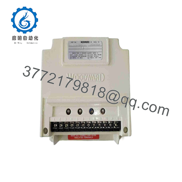
8290-044
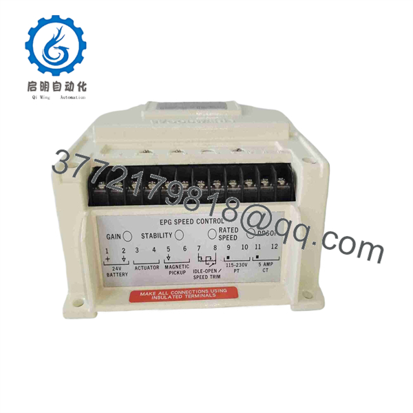
8290-044
Frequently Asked Questions (FAQ)
Q: What does the Woodward 8290-044 control?
A: The 8290-044 is an EPG speed-control unit for a 24 VDC engine governor system. It receives flywheel or gear speed feedback from a magnetic pickup and commands an EPG actuator to position the engine fuel-control linkage. It is used for closed-loop speed control on engines and generator packages.
Q: Is the 8290-044 a 12 VDC or 24 VDC controller?
A: The 8290-044 is commonly identified as the 24 VDC EPG speed-control version. The applicable 24 VDC supply range is 20–32 VDC, used with 524 or 1724 actuator families as required by the mechanical work-output demand. Confirm the exact nameplate and actuator part number before applying power.
Q: Do I need software to configure the 8290-044?
A: No. This is an analog governor controller. It uses physical adjustments for functions such as rated speed, idle speed, gain, stability, and—on applicable configurations—droop or start-fuel behavior. That makes replacement straightforward only if you carefully document the old settings before removal.
Q: Can I replace the 8290-044 with a different Woodward EPG controller?
A: Not automatically. Match the full control part number, battery voltage, actuator family, required work output, governor mode, load-sensing requirement, speed-reference range, and wiring diagram. A controller from a different EPG application may physically resemble this unit yet run the actuator incorrectly or lack the required droop function.
Q: What magnetic pickup checks should I make before replacing the controller?
A: Check pickup mounting, bracket rigidity, air gap, wiring, and resistance first. Woodward specifies a 0.25–1.0 mm pickup gap and a 50–350 Ω resistance check. During cranking, the pickup signal should reach at least 1.5 VAC RMS at the controller input. A weak signal can cause no-start, speed instability, or false overspeed symptoms.
Q: Can I hot-swap a 8290-044 while the engine is running?
A: No. Removing power or disconnecting the actuator circuit while the engine is running can cause fuel shutdown, uncontrolled speed response, or a trip. Complete the change during an approved shutdown, isolate power, verify the independent overspeed protection, and recommission the governor under controlled conditions.
Q: Why does the engine hunt after I install a replacement controller?
A: Hunting usually comes from gain and stability settings, poor actuator linkage, unstable fuel delivery, or noisy MPU feedback—not necessarily a defective replacement unit. Start with the documented adjustment settings, verify the magnetic pickup and actuator mechanics, then tune in small increments. Turning pots aggressively is the fastest way to lose a stable baseline.
Q: Why can New Surplus 8290-044 inventory cost less than current factory equipment?
A: New Surplus usually means unused original inventory released from an OEM spare shelf, canceled project, distributor excess, or stored maintenance stock. It may not include current factory support, original harnesses, commissioning records, or factory warranty. Before purchase, request photos of the exact nameplate, terminal condition, origin and condition statement, power-on test record, MPU signal simulation test, actuator-output load test, warranty terms, and actual shipping lead time.



