
 WhatsApp: +86 16626708626
 Email:
  Phone: +86 16626708626
Description
Key Technical Specifications
| Parameter | Value |
|---|---|
| Model | Woodward 8406-121 |
| Product family | EGCP-2 Engine Generator Control Package |
| Product type | Microprocessor-based generator controller |
| Primary application | Small- to medium-sized diesel or gas generator sets |
| Operating modes | Stand-alone, utility-parallel, and multi-generator parallel |
| Maximum EGCP-2 network size | Up to eight unattended generator sets |
| DC supply range | 9–32 VDC SELV |
| Nominal DC power consumption | 13 W or less |
| Maximum DC power consumption | 20 W |
| Supply current at 12 VDC nominal | 1.08 A |
| Supply current at 24 VDC nominal | 542 mA |
| Supply current at 32 VDC | 406 mA |
| PT input range | 50–150 VAC |
| CT input range | 0–5 A RMS |
| Generator frequency range | 45–65 Hz nominal application range |
| Generator synchronizing | Automatic generator-to-bus and generator-to-generator synchronizing |
| Real-power control | kW load control and load sharing |
| Reactive-power control | kVAR/PF control and reactive-load sharing |
| Engine control | Automatic start, stop, warm-up, cooldown, and shutdown logic |
| Generator protection | Voltage, frequency, current, reverse power, and related protection functions |
| Engine protection | Configurable engine alarm and shutdown monitoring |
| Communications | Modbus-capable serial communications |
| Communication interfaces | RS-485 and RS-422 |
| Front-panel interface | Two backlit LCD displays with keypad |
| Alarm indication | Red alarm/shutdown LED |
| Operating temperature | −20 to +70 °C |
| Storage temperature | −40 to +105 °C |
| Software family | 5418-149 application software |
| Field software upgrade | 8406-121 revisions A–G upgradeable to Revision H application level |
| Download interface | Woodward 5417-551 RS-232 to RS-422 cable or equivalent |
| Approximate dimensions | 282 × 358 × 69 mm |
| Approximate weight | 2.82 kg |
| Product status | Legacy / limited aftermarket availability |
The Woodward 8406-121 is the EGCP-2 version with a 50–150 VAC potential-transformer input. It operates from 9–32 VDC, accepts 0–5 A RMS CT input, and provides generator synchronization, kW and kVAR control, engine and generator protection, automatic sequencing, and Modbus communications. Do not confuse it with the 8406-120, which uses a 150–300 VAC PT input range.
Product Introduction
The Woodward 8406-121 is an EGCP-2 digital engine-generator controller for diesel or gas generator sets. It automates engine start and stop, generator synchronization, breaker control, kW load sharing, kVAR or power-factor control, generator protection, and engine protection in stand-alone or paralleled power systems.
This specific 8406-121 version accepts 50–150 VAC PT sensing inputs and 0–5 A RMS CT inputs. It is commonly used in small- and medium-generator applications where multiple units operate for standby, peak-shaving, or base-load duty. A network of EGCP-2 controls can manage up to eight unattended generator sets.
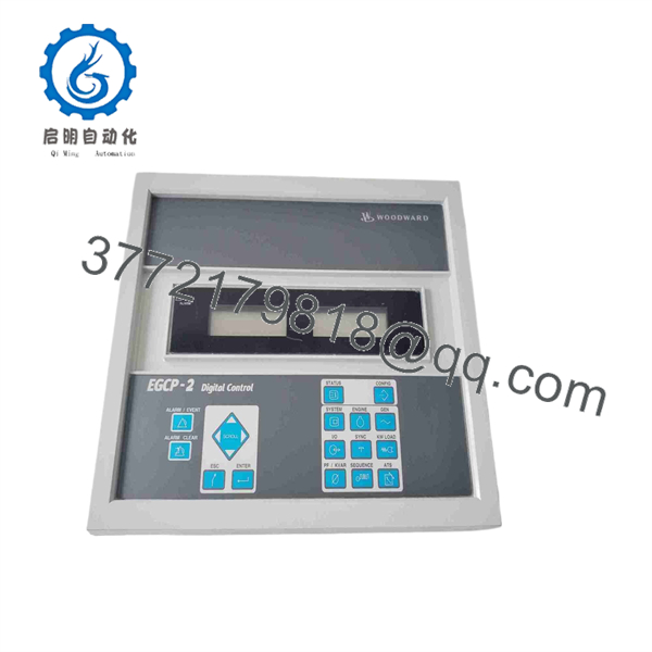
8406-121
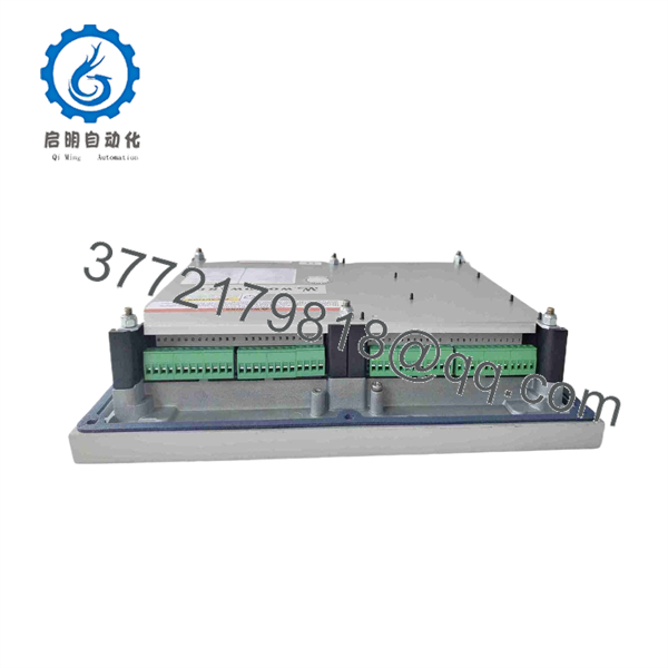
8406-121
Troubleshooting Quick Reference
| Symptom | Possible Cause | Relevance to this Part | Quick Check Method | Recommendation |
|---|---|---|---|---|
| EGCP-2 display is blank | Missing DC supply, blown fuse, poor negative return, undervoltage during cranking, failed controller | ⚠️ Medium | Measure supply directly at the controller input during idle, crank, and breaker-close events. Confirm the voltage remains within 9–32 VDC. | Check battery, charger, DC fuse, grounding, and harness before replacing the controller. |
| Controller powers up but generator will not start | Auto mode disabled, start permissive open, E-stop active, engine ECU fault, start relay circuit fault | ❌ Low | Check operating mode, start request status, E-stop loop, engine alarms, and starter circuit voltage. Review the active alarm page. | A start failure is often outside the controller. Verify engine safeties and start-circuit wiring before replacing the 8406-121. |
| Generator starts but does not build voltage | AVR failure, excitation circuit fault, breaker open, PT wiring issue, generator fault | ❌ Low | Measure generator terminal voltage independently and compare it with the displayed voltage. Confirm PT fuses, wiring, ratio, and phase assignment. | Check AVR, excitation, PT circuit, and generator condition before changing the controller. |
| Displayed voltage is incorrect | Wrong PT ratio, PT wiring error, blown sensing fuse, phase-to-phase versus phase-to-neutral configuration mismatch | ⚠️ Medium | Compare a calibrated meter reading at the generator terminals with the displayed value. Confirm the configured PT ratio and the actual 50–150 VAC sensing secondary. | Correct PT wiring or scaling. Do not install an 8406-121 on a 150–300 VAC PT-secondary system without an appropriate transformer arrangement. |
| Generator will not synchronize | Incorrect phase rotation, PT polarity error, frequency mismatch, governor/AVR control problem, synchronizer settings | ⚠️ Medium | Compare generator and bus phase sequence with an approved phase-rotation meter. Review displayed frequency, voltage difference, phase angle, and synchronizing alarms. | Fix PT phasing, governor speed control, and AVR voltage matching first. Do not defeat breaker-close permissives. |
| Breaker close command occurs but breaker does not close | Dead breaker coil, missing control voltage, anti-pump lockout, open interlock, failed relay output | ⚠️ Medium | Check the breaker-close output state, then measure voltage at the breaker close coil. Inspect breaker auxiliary contacts and interlocks. | Use the breaker schematic. If the controller output commands correctly but coil voltage is absent, trace the external control circuit. |
| Generator closes but immediately trips | Reverse power, over/under voltage, over/under frequency, CT polarity error, protection setting issue | ⚠️ Medium | Capture the first-out alarm and event sequence. Verify CT polarity and ratio, PT phasing, measured kW direction, voltage, and frequency. | Do not reset repeatedly. Correct the initiating protection cause before re-closing the breaker. |
| One generator carries all kW load | CT polarity or scaling error, load-share network issue, governor bias issue, incorrect kW setpoint | ⚠️ Medium | Compare CT phase/polarity, displayed kW, load-share mode, and governor raise/lower command response across all sets. | Check CT wiring and generator governor response before replacing the . A reversed CT can make a healthy controller drive load in the wrong direction. |
| Reactive load sharing is unstable | AVR droop/reactive-sharing setup error, PT polarity error, incorrect kVAR/PF settings, AVR instability | ⚠️ Medium | Trend kVAR, PF, voltage reference, and AVR command behavior. Compare PT wiring and reactive-sharing parameters across all controllers. | Correct AVR and PT configuration before modifying settings. Reactive instability is usually a complete control-loop problem. |
| Modbus or supervisory communication is lost | RS-422/485 wiring issue, duplicate address, termination error, cable shield problem, wrong port configuration | ⚠️ Medium | Verify device address, baud rate, parity, port selection, cable polarity, and end-of-line termination. Check whether the control finishes booting normally. | Correct the communications network before replacing hardware. Older boot code can lock during startup when a Modbus signal is present on the RS-422 port. |
| Unit reboots during deceleration or shutdown | Legacy application software issue, low DC voltage, internal fault, wiring disturbance | ✅ High | Record the displayed boot code and software revision. Monitor DC supply while frequency decreases through the shutdown sequence. | Check for application software 5418-149 Revision G availability and back up the configuration before upgrades. Woodward documented an older reboot condition during slow deceleration near 21.35–21.50 Hz. |
| Replacement controller operates but system behavior differs | Configuration not restored, wrong firmware revision, PT/CT settings wrong, calibration mismatch, incorrect I/O mapping | ✅ High | Upload the existing configuration before removal. Compare configuration, calibration, software revision, PT/CT ratios, protection settings, operating mode, and I/O assignment. | Never commission a factory-default replacement on a live generator system. Restore and validate the approved configuration under a controlled test plan. |
❗ PT-input warning: The 8406-121 is the 50–150 VAC PT-input version. The 8406-120 uses 150–300 VAC PT inputs. They are not interchangeable just because the housing and connector layout appear similar. Confirm actual PT secondary voltage at the controller terminals before applying power.
❗ CT-polarity warning: Document CT phase assignment, polarity marks, ratio, and grounded side before removal. Reversed CT polarity can reverse measured kW direction, block proper load sharing, or create reverse-power trips after breaker closure.
❗ Firmware warning: Record the unit’s boot code and application software revision before installing a replacement. Woodward documented a field upgrade path from 8406-121 Revisions A–G to Revision H using application software 5418-149 Revision G. The application update retains existing configuration and calibration settings, but boot code changes cannot be downloaded in the field.
❗ Live-system warning: Do not remove or replace an while it has authority over an online generator breaker, start circuit, or load-sharing system. Coordinate the work with operations, switchgear control, protection engineering, and the responsible generator-control engineer. Use the approved outage, bypass, lockout, and functional-test procedure.
Keep these checks in mind and you will save yourself 90% of typical rework time. If you are stuck, send technical support photos of the nameplate and revision, displayed alarm pages, PT and CT terminal wiring, DC supply measurements, serial network details, controller configuration archive, and event logs.
Frequently Asked Questions (FAQ)
Q: What is the Woodward 8406-121 used for?
A: The Woodward 8406-121 is an generator controller. It manages engine operation, synchronizing, breaker control, kW load sharing, kVAR or power-factor control, automatic sequencing, generator protection, engine protection, and supervisory communications for diesel or gas generator sets.
Q: What is the difference between Woodward 8406-121 and 8406-120?
A: The critical difference is PT sensing range. The 8406-121 accepts 50–150 VAC PT inputs, while the 8406-120 accepts 150–300 VAC PT inputs. Verify the actual PT secondary voltage and the released wiring drawings. Installing the wrong version can produce incorrect sensing, failed protection calibration, or damage.
Q: Can the 8406-121 operate a single generator without paralleling?
A: Yes. The can operate as a stand-alone generator controller. It also supports utility-parallel and multi-generator applications when correctly configured with compatible governors, AVRs, breaker circuits, PT/CT sensing, and load-sharing networks.
Q: How many generators can an system control?
A: A network of controllers can control up to eight unattended generator sets for backup, peak-shaving, or base-load applications. Final system capacity depends on the released design, communications topology, switchgear, protective devices, and application configuration.
Q: Will I lose the generator settings when I replace an 8406-121?
A: You can, unless you upload and archive the installed configuration before removal. The replacement needs the correct PT and CT ratios, protection thresholds, engine sequence settings, breaker logic, synchronizing values, kW/kVAR settings, communications address, and I/O configuration. The hardware part number alone does not restore the application.
Q: Can I hot-swap the Woodward 8406-121?
A: No. Treat it as a planned generator-control outage item. Removing it can interrupt engine control, breaker control, synchronization, load-sharing commands, alarms, and protective functions. Isolate the generator, establish the correct operating state, and follow the approved site procedure before replacement.
Q: Does the 8406-121 support Modbus communications?
A: Yes. The platform supports Modbus-capable serial communications using RS-422 and RS-485 interfaces. Verify network addressing, cable polarity, termination, baud rate, and software/boot revision. The documented Revision 2.0 boot code addresses a startup lockup that could occur when a Modbus signal was present on the RS-422 port during boot.
Q: Why is New Surplus 8406-121 inventory less expensive than current factory hardware?
A: New Surplus generally means unused original inventory obtained from excess MRO spares, canceled projects, distributor liquidation, or stored OEM stock. It may not include current factory support, terminal plugs, cables, software tools, the original carton, or a current warranty. Before purchase, request exact-unit photos, revision and software information, nameplate details, PT-input confirmation, power-on test results, keypad/display test, serial communication test, I/O simulation evidence, warranty terms, and actual shipping lead time.



