
 WhatsApp: +86 16626708626
 Email:
  Phone: +86 16626708626
Description
Key Technical Specifications
| Parameter | Value |
|---|---|
| Manufacturer | Woodward |
| Part Number | 8440-1849 |
| Product Family | MFR-15 |
| Product Type | Multifunction Generator Protection Relay |
| Configuration | MFR1515B/BCIZMPMPSSBSB01UUSU07 |
| Controller Generation | H8 microprocessor |
| Primary Application | Generator protection and control |
| Equipment Class | MFR-15 multifunction relay |
| Legacy Status | Obsolete |
| Last-Time-Buy Date | January 23, 2015 |
| Replacement Path | 8440-1936 / 8444-1074 / 8444-1075 |
| Installation | Generator control/protection panel |
| CT/PT Inputs | Configuration-dependent; verify original drawings |
| Discrete I/O | Configuration-dependent |
| Relay Outputs | Configuration-dependent |
| Communication | Configuration-dependent |
| Exact Ratings | Verify from the complete configuration and nameplate |
The 8440-1849 is identified in legacy Woodward cross-reference records as MFR1515B/BCIZMPMPSSBSB01UUSU07, an MFR-15 multifunction relay from the older H8 microprocessor generation. The documented replacement combination is 8440-1936 / 8444-1074 / 8444-1075.
The part is listed as obsolete, with a last-time-buy date of January 23, 2015. That makes actual nameplate and configuration verification particularly important when sourcing unused legacy inventory.
Product Introduction
The Woodward 8440-1849 is an MFR-15 multifunction generator protection relay, configured as MFR1515B/BCIZMPMPSSBSB01UUSU07. It belongs to Woodward’s legacy H8-generation equipment used in generator monitoring, control, and protection applications.
The documented migration path involves 8440-1936 together with 8444-1074 and 8444-1075. This should be treated as an engineered replacement rather than a simple plug-in substitution. CT/PT scaling, protection functions, relay assignments, breaker control, communications, and panel wiring need to be mapped before commissioning.
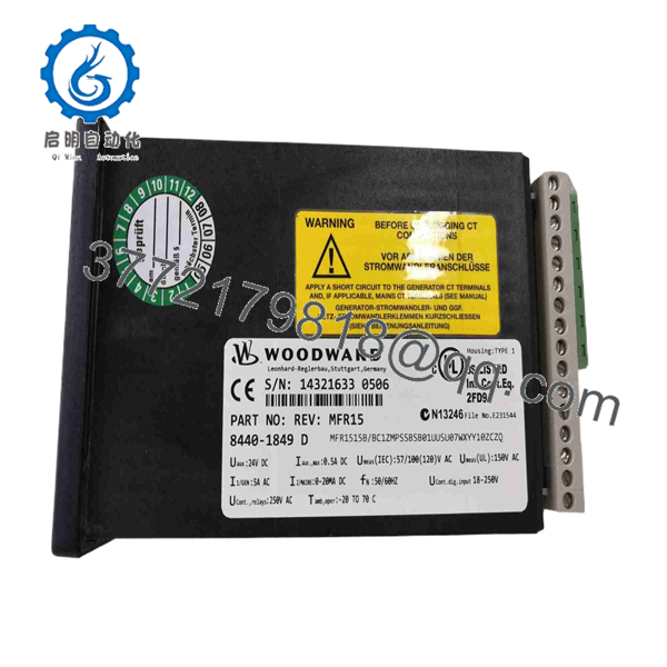
8440-1849
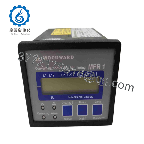
8440-1849
Installation & Configuration Guide
Stage 1: Pre-Installation Preparation
Estimated time: 30–45 minutes
- Notify operations and place the generator in its approved maintenance state.
- Apply the site’s LOTO procedure.
- Isolate control power and applicable generator energy sources.
- Verify absence of hazardous voltage with a properly rated multimeter.
- Wear an ESD wrist strap when handling the relay.
- Prepare:
- Digital multimeter
- PH1 screwdriver
- Wire labels
- Camera/phone
- Generator single-line diagram
- Existing protection settings
- MFR-15 configuration records
- Photograph the complete front panel and terminal wiring.
- Record the complete part number and configuration string.
- Record CT ratios, VT/PT ratios, relay assignments, breaker-control circuits, and communications settings.
⚠️ Do not identify this unit only as “MFR-15.” The complete configuration string determines the actual hardware and functional arrangement.
Stage 2: Removing the Old Module
Estimated time: 20–30 minutes
- Confirm the generator cannot start or close its breaker unexpectedly.
- Verify all required circuits are isolated.
- Label every external connection.
- Photograph each terminal group.
- Identify CT circuits separately from voltage-sensing circuits.
- Follow the site’s CT shorting procedure before disconnecting current-transformer wiring.
- Disconnect control and communication wiring.
- Release the mounting hardware.
- Remove the 8440-1849 carefully.
- Inspect terminal blocks and wiring for heat damage, corrosion, or loose conductors.
- Keep the original unit until commissioning is complete.
⚠️ Never leave an energized CT secondary open. Follow the generator protection system’s approved CT isolation procedure.
Stage 3: Installing the New Module
Estimated time: 30–60 minutes
- Verify the replacement part number and configuration.
- Confirm whether the replacement is another 8440-1849 or an engineered migration.
- Mount the unit securely.
- Reconnect control power.
- Reconnect CT inputs according to the approved drawings.
- Reconnect VT/PT inputs.
- Reconnect breaker-control outputs.
- Reconnect discrete inputs and outputs.
- Reconnect communications.
- Verify grounding and shielding.
- Check terminal torque.
- Perform continuity and polarity checks.
If migrating from 8440-1849:
- Do not assume the replacement wiring is pin-for-pin identical.
- Map every input and output to the replacement architecture.
- Transfer protection settings manually.
- Verify CT/PT ratios.
- Verify pickup values and time delays.
- Verify breaker-control logic.
- Verify generator and bus sensing.
- Verify communications mapping.
- Perform functional testing before energizing the generator.
Woodward’s legacy cross-reference specifically identifies 8440-1936 / 8444-1074 / 8444-1075 as the replacement combination for 8440-1849.
Stage 4: Power-On & Testing
Estimated time: 60–120 minutes
- Complete a pre-power inspection.
- Verify control-power voltage.
- Energize the protection system.
- Check diagnostic indications.
- Verify measured generator voltage.
- Verify current measurements.
- Verify frequency and phase measurements.
- Confirm CT/PT scaling.
- Test discrete inputs.
- Test relay outputs using the approved commissioning procedure.
- Verify breaker-control functions.
- Verify alarm and trip functions.
- Check all protection settings.
- Verify communications if installed.
- Perform a controlled generator start.
- Verify synchronization and breaker operation.
- Record final commissioning values.
⚠️ Do not perform a live breaker operation merely to test an output contact. Use an approved protection-relay commissioning procedure with operations control.
Frequently Asked Questions (FAQ)
1. What is Woodward 8440-1849?
The 8440-1849 is a Woodward multifunction generator protection relay, with the documented configuration MFR1515B/BCIZMPMPSSBSB01UUSU07. It belongs to the older H8 microprocessor generation.
2. Is 8440-1849 obsolete?
Yes. Legacy cross-reference information lists the unit as obsolete, with a last-time-buy date of January 23, 2015.
3. What replaces Woodward 8440-1849?
The documented replacement path is 8440-1936 / 8444-1074 / 8444-1075. Because this is a replacement combination rather than a single identical part number, the application requires engineering review before installation.
4. Can I directly replace 8440-1849 with 8440-1936?
Do not assume a direct pin-for-pin replacement. The replacement architecture should be checked against CT/PT circuits, discrete I/O, relay functions, breaker logic, communications, and protection settings.
5. What does the MFR1515B configuration identify?
The MFR1515B/BCIZMPMPSSBSB01UUSU07 string identifies the specific configuration associated with 8440-1849. For procurement, use the complete configuration string rather than ordering only an “,” because configurations can differ.
6. Can I still buy a new original 8440-1849?
Unused legacy inventory may still exist even though the part is obsolete. “New” should be verified as unused physical stock, not interpreted as current production. Request photographs of the actual nameplate, serial number, packaging, and storage condition.
7. What should I verify before ordering?
Verify the complete 8440-1849 part number, configuration string, serial number, hardware revision, terminal arrangement, CT/PT ratios, protection settings, and generator-control architecture. If an original unit is unavailable, compare the application against the documented 8440-1936 / 8444-1074 / 8444-1075 migration path rather than selecting a replacement by physical appearance alone.



