
 WhatsApp: +86 16626708626
 Email:
  Phone: +86 16626708626
Description
Key Technical Specifications
| Parameter | Specification |
|---|---|
| Manufacturer | Woodward |
| Part Number | 8444-1019F |
| Product Family | UMT 1 |
| Configuration | UMT 1/A6 |
| Measurement Voltage | 100 VAC nominal |
| Maximum Measurement Voltage | 150 VAC according to available nameplate data |
| Current Input | 5 A AC |
| Current Measurement | True RMS |
| Analog Outputs | 6 isolated outputs |
| Output Range | Configurable -20 to 20 mA, 0 to 20 mA, or 4 to 20 mA |
| Auxiliary Supply | 24 VDC |
| Supply Range | 8–30 VDC |
| Measurement Frequency | 50/60 Hz |
| Accuracy | Class 0.5 |
| Operating Temperature | -20 to +70 °C |
| Front Protection | IP42 |
| Rear Protection | IP21 |
| Dimensions | 96 × 72 × 130 mm |
| Approx. Weight | 0.8 kg |
Woodward’s UMT 1 catalog specifies true-RMS measurement, Class 0.5 accuracy, configurable isolated analog outputs, 24 VDC auxiliary supply, and the A6 configuration with six analog outputs. The catalog specifically maps 100 VAC / 5 A to part number 8444-1019.
A surviving UMT 1 nameplate record for 8444-1019 additionally identifies the unit as UMT115B/A6, with 57/100 (120) VAC measurement, 5 A AC current input, 24 VDC auxiliary supply, 50/60 Hz operation, and -20 to +70 °C operating temperature.
Product Introduction
The Woodward 8444-1019F is a UMT 1/A6 multifunction measuring transducer designed for electrical measurement in power-generation and distribution systems. It accepts voltage and current measurement signals and converts measured values into isolated analog outputs for use by plant controllers, meters, PLC/DCS systems, and supervisory equipment. Woodward documentation assigns 8444-1019 to the 100 VAC, 5 A version with six analog outputs.
The UMT 1 platform uses true-RMS measurement and Class 0.5 accuracy. Depending on configuration, measured voltage and current can be used to derive active power, reactive power, apparent power, power factor, kWh, and kvarh. The six-output A6 configuration is useful where several independent electrical measurements must be transmitted to downstream control or monitoring equipment.
Lifecycle consideration: 8444-1019 is listed as discontinued/obsolete in current industrial-part databases. This makes revision matching, electrical-input configuration, and physical inspection particularly important when sourcing a replacement.
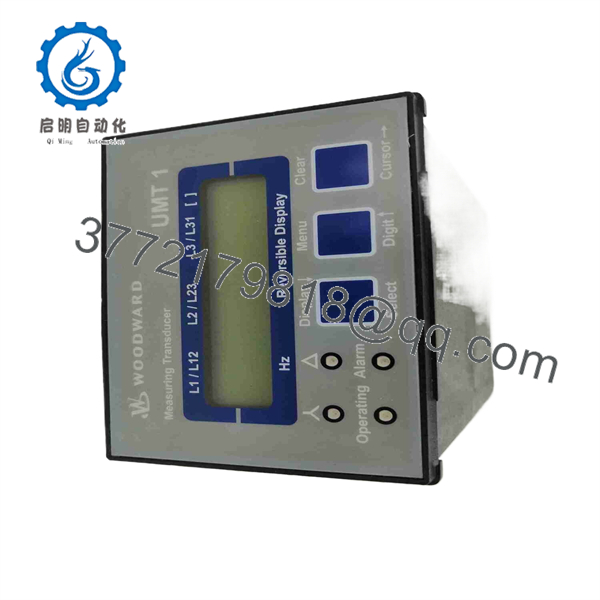
8444-1019F
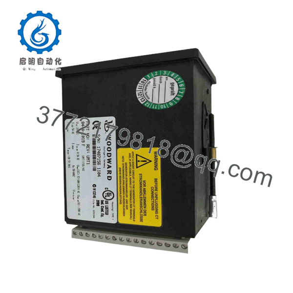
8444-1019F
Installation & Configuration Guide
Stage 1 — Pre-Installation Preparation
Estimated time: 15–20 minutes
- Notify operations and place the associated electrical measurement circuit in a safe maintenance state.
- Apply LOTO before disconnecting voltage or current measurement wiring.
- Verify the auxiliary 24 VDC supply is isolated.
- Allow at least 5 minutes for connected equipment capacitors to discharge where applicable.
- Wear an ESD wrist strap when handling the electronic transducer.
- Prepare a PH1 screwdriver, multimeter, wire labels, smartphone/camera, and the existing wiring documentation.
- Photograph the existing UMT 1 wiring and front-panel configuration before removal.
- Confirm that the replacement is specifically 8444-1019F / UMT 1/A6 and that its voltage/current configuration matches the installed system.
⚠️ Do not substitute another 8444-series UMT 1 solely because the housing or front panel looks identical. Woodward used different voltage, current, output, and communication configurations within the family.
Stage 2 — Removing the Old Module
Estimated time: 10–15 minutes
- Remove the front-panel mounting hardware or release the panel retaining mechanism.
- Label every voltage, CT-current, auxiliary-power, and analog-output conductor.
- Never open an energized CT secondary circuit. Confirm the CT circuit is correctly isolated or shorted according to the plant’s protection procedure before disconnecting current-input wiring.
- Disconnect the terminals carefully without pulling on the conductors.
- Release the mounting hardware and withdraw the UMT 1 straight from the panel.
- Inspect the wiring terminals for overheating, oxidation, loose conductors, or insulation damage.
- Retain the removed unit until the replacement has passed commissioning tests.
Stage 3 — Installing the New Module
Estimated time: 15–25 minutes
- Confirm the replacement nameplate reads 8444-1019 and the revision is F or an approved equivalent.
- Verify the input configuration: 100 VAC measurement / 5 A AC current.
- Compare the terminal arrangement against the original unit and the applicable Woodward documentation.
- Reconnect the auxiliary 24 VDC supply with correct polarity.
- Reconnect voltage and current measurement circuits using the original labels.
- Reconnect the six analog-output circuits according to the plant’s I/O drawings.
- Check terminal torque and conductor seating.
- Confirm that CT polarity and phase identification have not changed.
- Inspect the completed wiring against the photographs and wiring checklist.
⚠️ Do not assume revision F has identical internal configuration to another UMT 1 revision without checking the applicable documentation. Available market listings confirm Revision F units exist, while Woodward’s published catalog primarily documents the underlying 8444-1019 configuration rather than the revision suffix.
Stage 4 — Power-On & Testing
Estimated time: 20–40 minutes
- With the measurement circuits still controlled, use a multimeter to verify the auxiliary supply and check for unintended shorts.
- Energize the 24 VDC auxiliary supply.
- Confirm the UMT 1 display starts normally and inspect the front-panel indication.
- Apply the measurement voltage and verify that displayed values correspond with calibrated plant instruments.
- Confirm current readings for each connected phase.
- Check each of the six analog outputs individually at the receiving PLC/DCS/monitoring system.
- Verify engineering-unit scaling at the receiving input card.
- Check calculated electrical values such as power and power factor where these functions are configured.
- Record the final measured values as part of commissioning documentation.
Troubleshooting note: If voltage/current readings are incorrect, first check CT polarity, phase assignment, input range, wiring, and analog-output scaling before replacing the transducer. A UMT 1 with the wrong input configuration can appear electrically functional while producing incorrect plant measurements.
Frequently Asked Questions (FAQ)
1. What is Woodward 8444-1019F?
It is a Woodward UMT 1/A6 measuring transducer, configured for approximately 100 VAC measurement and 5 A AC current input, with six isolated analog outputs. Woodward’s catalog identifies 8444-1019 as the 100 VAC / 5 A A6 version.
2. Is 8444-1019F obsolete?
The underlying 8444-1019 part number is listed as obsolete in a Woodward legacy cross-reference, with last-time-buy ending January 23, 2015. Current surplus listings show Revision F and other revisions still circulating, so availability is primarily dependent on remaining stock.
3. Is 8444-1019F a digital speed controller?
No. The exact 8444-1019 configuration is a UMT 1 measuring transducer, not a Woodward digital speed governor. Some third-party listings incorrectly describe 8444-1019F as a digital speed-control unit; Woodward’s own catalog identifies 8444-1019 as a UMT 1/A6 measuring transducer.
4. What is the difference between 8444-1019 and other UMT 1 part numbers?
The 8444-series UMT 1 models use different electrical configurations. For example, Woodward lists 8444-1002 for 100 VAC / 5 A with an A3SU configuration, while 8444-1019 is the A6 configuration with six analog outputs. Other part numbers cover 400 VAC or 1 A versions.
5. Can I replace 8444-1019F with another UMT 1?
Only after checking the complete electrical configuration. Voltage input, current input, number/type of analog outputs, communication options, and terminal assignment must match the application. Do not treat the UMT 1 family as universally pin-compatible.
6. What condition should I expect when purchasing a 8444-1019F?
Condition varies by supplier. Current secondary-market listings show Revision F units offered as used or surplus, so the exact unit condition, revision, nameplate, and included accessories should be verified before purchase.
7. What should I verify before ordering?
Provide the supplier with the complete part number and revision, nameplate photograph, voltage/current configuration, and required analog-output configuration. For an obsolete UMT 1, these details are more reliable than matching the basic “8444-1019” number alone.



