
 WhatsApp: +86 16626708626
 Email:
  Phone: +86 16626708626
Description
Key Technical Specifications
| Parameter | Value |
|---|---|
| Part Number | 9905-973 |
| Manufacturer | Woodward |
| Product Family | LinkNet |
| Product Type | RTD input module |
| Input Function | Resistance temperature detection |
| Network | LinkNet |
| Communication Architecture | LON-based |
| Supply | 24 VDC |
| Application | Temperature monitoring |
| Installation | LinkNet distributed I/O system |
| System Generation | Legacy Woodward control architecture |
| Lifecycle | Legacy / obsolete family |
| Condition | New Surplus or Refurbished, depending on stock |
Technical verification note: Public Woodward documentation confirms the LinkNet family and its RTD-input variants, but the sources reviewed do not provide enough OEM-level information to safely state the exact channel count, RTD resistance range, accuracy, or terminal assignment for 9905-973 specifically. Those values should be confirmed from the module label and applicable Woodward manual before installation.
Product Introduction
The Woodward 9905-973 belongs to the LinkNet family of distributed I/O hardware used with legacy Woodward control systems. LinkNet nodes communicate with the associated controller through a LON-based network and provide dedicated field-signal interfaces for turbine and engine control applications.
For a 9905-973 replacement, the complete part number is important. Verify the installed module’s input type, channel configuration, network connection, terminal arrangement, and controller compatibility before treating another LinkNet module as a substitute.
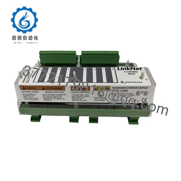
9905-973
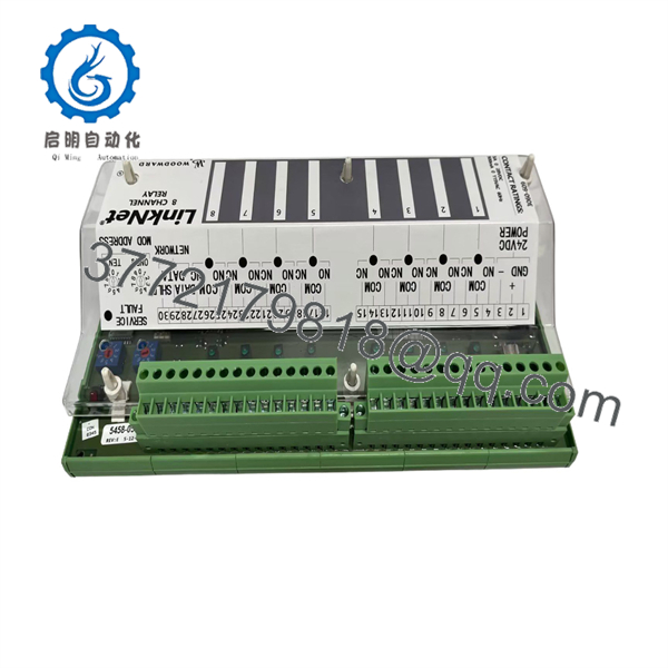
9905-973
Installation & Configuration Guide
Stage 1: Pre-Installation Preparation — About 10 Minutes
⚠️ Safety First: Place the turbine or engine control system in the approved maintenance state. Apply the site’s LOTO procedure before disconnecting the LinkNet module.
Tools Required:
- ESD wrist strap
- Digital multimeter
- Appropriate screwdriver
- Wire labels
- Smartphone/camera
- Approved Woodward system documentation
Data Backup:
- Record the complete 9905-973 part number and revision.
- Photograph the module and all terminal connections.
- Record the LinkNet node address.
- Identify every connected temperature channel.
- Record the corresponding field-device tags.
- Photograph the network connection and cable routing.
- Retain the original module until commissioning is complete.
Stage 2: Removing the Old Module — About 5–10 Minutes
- Confirm the controlled equipment is in a safe maintenance state.
- Isolate the module’s 24 VDC supply.
- Verify the supply is de-energized with a multimeter.
- Label each field connection.
- Photograph the wiring before disconnecting it.
- Disconnect the field wiring carefully.
- Disconnect the LinkNet communication connection.
- Release the module from its mounting arrangement.
- Inspect the connector and mating interface for damage or contamination.
⚠️ Do not rely on wire colors or memory. Legacy installations are often modified during years of service.
Stage 3: Installing the New 9905-973 — About 10 Minutes
- Verify the exact 9905-973 part number.
- Compare the replacement with the removed module.
- Confirm connector locations and mechanical dimensions.
- Install the module in the original approved location.
- Reconnect the LinkNet network connection.
- Reconnect each field circuit according to the original photographs and wiring diagram.
- Verify the node/address configuration.
- Secure all terminals.
- Inspect for loose conductors before energizing.
Configuration Clone — Critical:
- LinkNet node address
- Field-channel assignment
- Sensor type
- Controller I/O mapping
- Alarm configuration
- Existing temperature scaling
- Network configuration
Self-Checklist:
- Correct 9905-973 verified
- Node address documented
- Field wiring matched
- Network cable secured
- Sensor assignments verified
- Terminals tightened
- Original configuration available
Stage 4: Power-On & Testing — About 10–20 Minutes
- Perform a complete visual inspection.
- Verify the 24 VDC supply.
- Energize the LinkNet module according to the approved procedure.
- Check module status indications.
- Confirm communication with the Woodward controller.
- Verify the module is recognized at the correct network address.
- Check each connected temperature channel.
- Compare displayed values with an independent temperature reference where practical.
- Verify alarm status and channel mapping.
- Complete the site’s approved functional test before returning the control system to normal service.
⚠️ Do not stop at a communication check. A LinkNet module can communicate correctly while an individual field channel is incorrectly wired or assigned.
Frequently Asked Questions (FAQ)
Q1: What is the Woodward 9905-973?
The 9905-973 is a legacy Woodward LinkNet distributed I/O component associated with temperature/RTD signal acquisition. The exact channel configuration should be confirmed from the installed unit and applicable Woodward documentation.
Q2: Is 9905-973 part of the LinkNet system?
Yes. The part number belongs to the Woodward LinkNet hardware family. LinkNet uses a LON-based communication architecture for distributed control-system I/O.
Q3: Is 9905-973 interchangeable with another LinkNet RTD module?
Not automatically. Even when two modules perform similar temperature-input functions, their channel count, sensor range, terminal configuration, addressing, and controller mapping may differ. Verify the complete part number before substitution.
Q4: Is the 9905-973 obsolete?
It should be treated as legacy hardware. Woodward has discontinued the original LON-based LinkNet architecture for new applications, so availability of individual modules depends largely on remaining inventory and specialist spare-parts channels.
Q5: Can I hot-swap the 9905-973?
Do not assume hot-swapping is permitted. Follow the specific Woodward control-system maintenance procedure for the installed hardware and cabinet configuration.
Q6: What should I verify before buying a 9905-973?
Confirm the complete 9905-973 number, hardware revision, connector arrangement, field-input type, LinkNet node configuration, and physical condition. For a refurbished unit, request the test procedure and test report.
Q7: Why is exact identification particularly important for this part?
The LinkNet family contains several specialized I/O modules with similar physical formats. A visually similar replacement can communicate with the network but still provide the wrong field interface. For an operating turbine or engine, verify the I/O function and channel mapping before installation, not merely the mechanical fit.



