
 WhatsApp: +86 16626708626
 Email:
  Phone: +86 16626708626
Description
Key Technical Specifications
- Supply Voltage: 12/24 VDC nominal; 8–40 VDC operating range
- Intrinsic Consumption: Maximum 17 W
- Operating Temperature: −20 to +70 °C (standard specification)
- Storage Temperature: −30 to +80 °C
- Generator Control: Standby, prime-power, island-mode, and utility-parallel applications
- Multi-Unit Operation: Up to 32 gensets through networked sequencing
- Measuring Frequency: 50/60 Hz; 40–85 Hz measuring range
- Discrete Inputs: Isolated 12/24 VDC inputs; approximately 20 kΩ input resistance
- Relay Outputs: Isolated outputs; ratings depend on duty and load type
- Communications: CAN bus, RS-232, and RS-485 interfaces
- Housing: Plastic, flush-mount housing with integrated display
- Dimensions: Approximately 282 × 217 × 99 mm, W × H × D
- Front Protection: IP66 with screw fastening; IP54 with clamp fastening
- Rear Protection: IP20
- Weight: Approximately 1.85 kg
- Compliance: UL, cUL, CSA, and applicable EN requirements
Specifications vary by exact hardware package, suffix, current-transformer input option, and revision. Confirm the nameplate part number before ordering.
Product Introduction
The Woodward easYgen-3200 is an industrial genset controller for diesel or gas generator sets, including standby, prime-power, islanded, and utility-parallel applications. It combines engine control, generator measurement, synchronization, protection, breaker control, and operator display in one panel-mounted unit.
The controller is selected for multi-generator installations because the easYgen-3000 platform can coordinate up to 32 gensets through networked sequencing. CAN, RS-232, and RS-485 interfaces support integration with engine controls, external I/O, and plant monitoring systems.
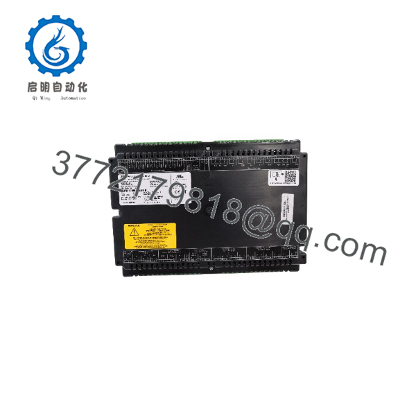
easYgen-3200
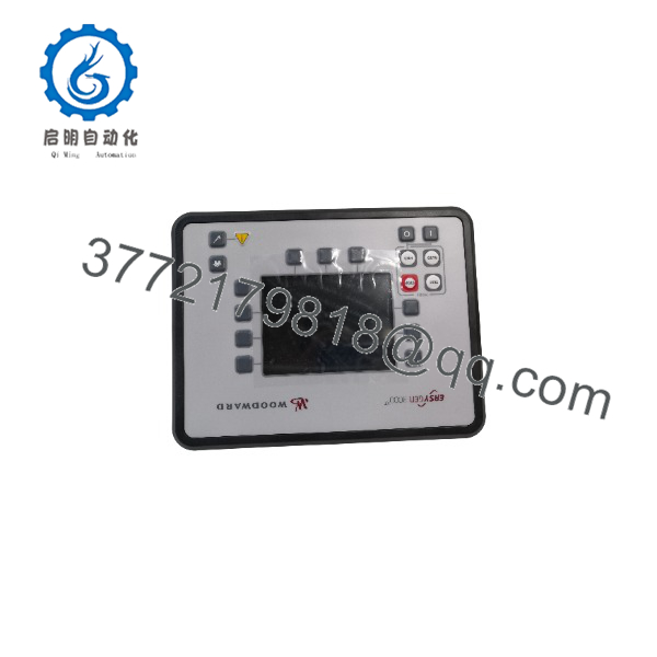
easYgen-3200
Troubleshooting Quick Reference
| Symptom | Possible Cause | Relevance to This Part | Quick Check Method | Recommendation |
|---|---|---|---|---|
| No display or LEDs after startup | Missing DC supply, blown fuse, reverse polarity, or internal controller fault | ⚠️ Medium | Measure 8–40 VDC directly at the controller supply terminals and verify polarity under load | Check the fuse, battery disconnect, and ground return before replacing the controller |
| Display remains dark but supply voltage is correct | Display or internal power-section failure | ✅ High | Confirm stable DC voltage during startup; inspect for current draw, heat damage, or cracked connectors | Replace only after external supply wiring and fuse protection pass inspection |
| Controller reboots during cranking | Battery voltage collapse or excessive electrical noise | ❌ Low | Monitor DC voltage at the controller with a meter or oscilloscope during engine cranking | Correct battery, grounding, suppression, or starter-circuit problems first |
| Generator voltage reads zero or incorrectly | PT wiring, sensing fuse, phase sequence, or configuration error | ❌ Low | Measure phase-to-phase and phase-to-neutral voltage at the controller sensing terminals; compare with the configuration | Do not condemn the controller until sensing wiring and parameters are verified |
| Current or power values are incorrect | CT ratio, CT polarity, phase assignment, or wiring fault | ❌ Low | Confirm CT secondary current, S1/S2 orientation, phase mapping, and programmed CT ratio | Correct CT installation and configuration before replacing the unit |
| Engine will not start | Start relay wiring, fuel solenoid circuit, permissive, or shutdown alarm | ❌ Low | Check the start-output LED, relay contact voltage, emergency-stop chain, and active alarm list | Trace the complete start permissive circuit; the controller may only be reporting an external fault |
| Generator breaker will not close | Synchronization limits, dead-bus logic, breaker feedback, or interlock | ❌ Low | Compare phase, frequency, and voltage values; verify breaker command and auxiliary feedback inputs | Check synchronizing parameters and breaker wiring before changing hardware |
| CAN devices show communication loss | Incorrect baud rate, termination, address, wiring, or incompatible firmware | ⚠️ Medium | Check CAN-H/CAN-L polarity, shield termination, bus resistance, node addresses, and diagnostic counters | Match firmware and communication parameters across all networked devices |
| RS-485 communication fails | A/B reversal, missing termination, ground potential, or protocol mismatch | ❌ Low | Verify A/B polarity, shield practice, termination resistance, slave address, and baud/parity settings | Correct physical-layer settings and confirm the configured protocol |
| Digital inputs remain inactive | Incorrect input common, missing 12/24 VDC signal, or damaged field wiring | ❌ Low | Apply a known control voltage and verify the input status in the diagnostics screen | Test the field circuit at the terminal before replacing the controller |
| Relay output does not energize | Output logic, inhibit condition, relay contact failure, or external fuse fault | ⚠️ Medium | Check the commanded output status, coil voltage, contact continuity, and configured operating mode | Separate logic failure from contact-circuit failure with a continuity and voltage test |
| Configuration disappears after power loss | Battery-backed memory issue, incorrect save procedure, or corrupted parameters | ⚠️ Medium | Save a parameter backup, cycle power, and compare retained values with the original file | Back up the configuration before replacement and verify retention after commissioning |
A replacement controller may be unnecessary when the actual fault is a dead battery, open sensing fuse, incorrect CT polarity, missing breaker feedback, or a configuration mismatch. If the fault remains unclear, send technical support clear photos of the nameplate and terminals together with the alarm list, configuration file, firmware revision, and diagnostic logs.
Frequently Asked Questions (FAQ)
What is the Woodward easYgen-3200 used for?
It controls and protects engine-generator sets in standby, prime-power, islanded, and utility-parallel applications. Typical functions include engine start/stop, voltage and frequency monitoring, synchronization, breaker control, alarm handling, and generator protection.
Does every easYgen-3200 have the same hardware?
No. The easYgen-3200 name covers multiple hardware packages and option configurations. Differences may include current-transformer inputs, analog I/O, relay arrangements, communications options, housing style, temperature range, and firmware. Match the complete part number and suffix, not only “3200.”
Can I use a newer easYgen-3200 as a direct replacement?
Possibly, but do not assume plug-and-play compatibility. Verify terminal assignments, housing dimensions, I/O count, firmware compatibility, configuration-file support, CT/PT ranges, and communication settings. Woodward documentation identifies different package and option variants within the easYgen-3000 family.
Will the generator configuration remain after replacing the controller?
Do not rely on the replacement retaining the old settings. Export or document the existing configuration before removal, including nominal voltage, frequency, CT ratio, PT ratio, engine start delays, protection limits, breaker logic, CAN settings, and password levels. Photograph every DIP switch, jumper, terminal connection, and nameplate before disconnecting the old unit.
Can I hot-swap the easYgen-3200?
Treat it as a power-off replacement unless the exact Woodward installation instructions explicitly permit otherwise. Isolate the DC supply, disable automatic starting, secure the generator breaker, and verify that remote start commands cannot energize the engine while wiring is being changed.
Why is a surplus unit cheaper than buying from the factory?
A surplus unit may be unused OEM inventory, discontinued stock, or a unit removed from a project. The lower price does not prove a technical defect, but it does make traceability and testing important. Confirm whether the unit is factory sealed, new surplus, refurbished, or used; request photographs of the nameplate and packaging before purchase.
What should I verify before ordering?
Provide the complete Woodward part number, hardware or option code, serial number, firmware revision, display and housing style, supply voltage, CT input rating, required communication interfaces, and the application’s configuration file. Also confirm stock status, lead time, warranty duration, and whether a functional test report is included.



