
 WhatsApp: +86 16626708626
 Email:
  Phone: +86 16626708626
Description
Key Technical Specifications
| Parameter | Value |
|---|---|
| Manufacturer | Woodward |
| Product Family | easYgen-3000 |
| Model | easYgen-3500-5 |
| Current Version Examples | easYgen-3500-5/P1, easYgen-3500-5/P2 |
| P/N — P1 | 8440-1934 |
| P/N — P2 | 8440-1936 |
| Current Measurement | 3 × true RMS generator current |
| CT Rating | 5 A version |
| Voltage Measurement | 3-phase generator voltage; mains voltage; busbar voltage |
| Communication | CAN bus, CANopen, RS-485 Modbus RTU |
| CAN Interfaces | Up to 3 on easYgen-3500 |
| Configurable Discrete Inputs | Up to 12 |
| Configurable Discrete Outputs | Up to 22 |
| Configurable Analog Inputs | Up to 10 |
| Configurable Analog Outputs | Up to 5 |
| Load Sharing | Up to 32 gensets |
| Mains-Parallel Operation | Up to 32 units |
| Synchronization | GCB / MCB synchronization |
| Operating Modes | Automatic, Manual, Stop, Test |
| Event Recorder | 300 entries with real-time clock |
| Programming | PC configuration via Woodward Toolkit and service connection |
Woodward’s published feature data identifies the easYgen-3500 platform as supporting automatic/manual/test operation, generator and mains measurement, synchronization, load-dependent start/stop, interchange control, load/VAR sharing, configurable PID controllers, CAN communication, and Modbus RTU.
Product Introduction
The Woodward easYgen-3500-5 is a generator-set controller for applications requiring genset sequencing, synchronization, mains monitoring, breaker control, and power management. The “5” version uses 5 A current-transformer inputs. The platform supports multi-unit operation, including load sharing and mains-parallel applications.
For replacement work, do not order against “easYgen-3500-5” alone. The /P1 and /P2 variants have different Woodward part numbers. Woodward lists 8440-1934 for 3500-5/P1 and 8440-1936 for 3500-5/P2. Verify the existing rear-panel label before installation.
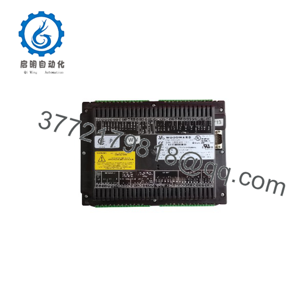
easYgen-3500-5
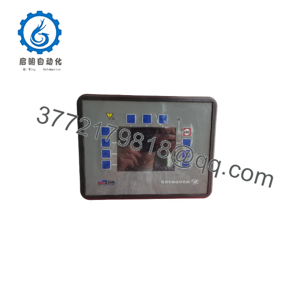
easYgen-3500-5
Installation & Configuration Guide
Stage 1: Pre-Installation Preparation — 5–10 minutes
⚠️ Safety First: Notify operations, place the generator system in a safe state, and apply the site’s lockout/tagout procedure before removing the controller. Do not assume that a genset controller can be safely removed while the panel remains energized.
Tools Required:
- ESD wrist strap
- PH1/PH2 screwdriver as applicable
- Digital multimeter
- Wire labels
- Smartphone or camera
- Appropriate terminal screwdriver
Data Backup:
- Record the complete Woodward part number from the rear-panel label.
- Determine whether the installed controller is
/P1or/P2. - Photograph all terminal wiring before removal.
- Photograph DIP switches, jumpers, and configuration labels.
- Record the controller firmware/application revision.
- Save the existing Toolkit configuration file if accessible.
- Record CT wiring and polarity carefully. A 5 A CT circuit should never be treated like an ordinary voltage input.
Woodward states that configuration files can be located using the part number shown on the rear-panel type sticker, with the applicable Toolkit revision selected for the controller.
Stage 2: Removing the Old Module — 5 minutes
- Isolate the controller according to the panel’s approved shutdown procedure.
- Verify the relevant DC supply is de-energized.
- Remove the front mounting hardware as applicable.
- Label every connector and conductor before disconnecting it.
- Disconnect terminals without pulling on the conductors.
- Release the mounting mechanism.
- Pull the controller straight out.
- Inspect the mating connectors for contamination, bent contacts, or mechanical damage.
⚠️ Keep the old controller beside the replacement until commissioning is complete. It provides the reference for wiring, revision identification, and configuration.
Stage 3: Installing the New Module — 5–10 minutes
- Verify the exact Woodward part number. For example, 8440-1934 identifies the 3500-5/P1 version, while 8440-1936 identifies the 3500-5/P2 version.
- Put on the ESD wrist strap.
- Compare terminal assignments against the applicable Woodward manual.
- Clone the documented configuration, including node addresses and application-specific settings.
- Check CT connections carefully. Confirm phase assignment and polarity.
- Insert the controller into its mounting position.
- Secure the mounting hardware.
- Reconnect wiring using the applicable terminal torque specification.
- Confirm communication wiring, especially CAN and RS-485 connections.
Self-Checklist:
- Exact part number verified
/P1or/P2variant verified- CT wiring verified
- CAN wiring verified
- Modbus wiring verified
- Configuration backed up
- Terminals secured
- Mounting hardware locked
Stage 4: Power-On & Testing — 10–20 minutes
- Check the DC supply and wiring for shorts before energizing.
- Power the controller with the generator and field outputs maintained in a safe commissioning state.
- Observe the display and status indications during boot.
- Connect Woodward Toolkit where required.
- Verify firmware/application revision.
- Confirm voltage and current measurements against calibrated test instruments.
- Verify phase sequence and measured frequency.
- Check CAN communication with connected Woodward devices.
- Check RS-485 Modbus communication if used.
- Test digital inputs and outputs without commanding unsafe breaker or engine operations.
- Verify synchronization parameters before attempting breaker closure.
- Conduct a controlled generator test and verify load-sharing behavior where applicable.
⚠️ Do not assume that an identical housing means an identical configuration. Woodward documents multiple hardware and revision changes within the easYgen-3000 family. Settings files can be shared between certain revisions, but parameters may be added or removed and new parameters may require manual verification.
For systems using the LS-5 breaker-control architecture, Woodward specifies CAN communication between the easYgen-3500 and LS-5 through CAN #3. Breaker behavior depends on the configured application structure and control logic.
Frequently Asked Questions (FAQ)
Can I hot-swap the Woodward easYgen-3500-5?
Do not treat the easYgen-3500-5 as a generic hot-swappable I/O module. For a controller replacement, follow the applicable Woodward installation procedure and site LOTO requirements. Removing power before replacement also prevents accidental breaker or engine-control commands during the changeover.
What is the difference between easYgen-3500-5/P1 and 3500-5/P2?
They are different variants with different Woodward part numbers. Woodward lists 8440-1934 for easYgen-3500-5/P1 and 8440-1936 for easYgen-3500-5/P2. Do not substitute one solely because the front-panel model designation appears similar. Verify the complete part number and application requirements first.
Is the 5 in easYgen-3500-5 related to the CT input?
Yes. The 3500 family includes both 1 A and 5 A current-input versions. Woodward’s ordering table identifies the 5 A version separately from the 1 A version. A replacement therefore needs to match the installed CT secondary rating.
Can the easYgen-3500 control multiple generators?
Yes. Woodward documents load/VAR sharing for up to 32 gensets on the easYgen-3500 platform and mains-parallel multiple-unit operation up to 32 units. The actual system limit still depends on the complete control architecture and configured equipment.
Will I lose the existing configuration when replacing the controller?
The physical replacement does not automatically reproduce the old controller’s application configuration. Back up the existing settings before removal whenever possible. Woodward notes that settings files may be shared across easYgen-3000 part numbers and revisions, but parameters can change between revisions and new parameters may require manual updating.
Is the easYgen-3500-5 obsolete?
The original easYgen-3500 platform is now part of Woodward’s legacy product ecosystem, with the easYgen-3500XT family providing newer replacement options for several older 3500 variants. Woodward specifically documents replacement paths from older easYgen-3500 P1/P2 controls to easYgen-3500XT P1/P2.
That does not mean every 3500-5 installation should automatically be converted to an XT controller. Wiring, I/O allocation, communication architecture, and application configuration must be checked. Woodward also documents wiring differences between the original 3400/3500 and the XT versions.
Why can a replacement easYgen-3500 require configuration work even when the model looks identical?
Firmware and hardware revisions can change parameter sets and application behavior. Woodward’s support documentation states that significant product changes can result in part-number changes, while smaller hardware and software changes can appear as revision-letter changes. Always record the installed revision before replacement rather than assuming the newest available unit is configuration-identical.



