
 WhatsApp: +86 16626708626
 Email:
  Phone: +86 16626708626
Description
Key Technical Specifications
| Parameter | Value |
|---|---|
| Manufacturer | Woodward |
| Model Number | EGCP-2 8406-121 |
| Product Type | Microprocessor-based engine generator control package |
| Power Supply | 9–32 Vdc (12/24 Vdc nominal) |
| Power Consumption | ≤13 W nominal, 20 W maximum |
| PT Voltage Input | 50–150 Vac true RMS |
| CT Current Input | 0–5 A rms |
| Generator Frequency Range | 40–70 Hz |
| Magnetic Pickup Input | 100–15,000 Hz |
| Process Input | 4–20 mA, 1–5 Vdc |
| Temperature/Pressure Inputs | 0–200 Ω sensors, 4–20 mA transducer, 0–5 V transducer |
| Communication Ports | RS-485, RS-422 |
| Communication Protocol | Modbus compatible communication |
| Relay Output Rating | 10 A, 250 Vac resistive / 10 A, 30 Vdc resistive |
| Operating Temperature | −20 to +70 °C (−4 to +158 °F) |
| Storage Temperature | −40 to +105 °C (−40 to +221 °F) |
| Humidity Rating | 95% at 20 to 55 °C |
| Dimensions (W × H × D) | 358 × 282 × 69 mm (14.1 × 11.1 × 2.7 in) |
| Mounting Type | Front panel mounting, sheet metal housing |
Product Introduction
The Woodward EGCP-2 8406-121 is a microprocessor-based engine generator control package designed for diesel and gas generator sets. It manages generator synchronization, load sharing, engine protection, generator protection, and automatic start/stop functions. The 8406-121 version uses a 50–150 Vac PT input range for generator voltage sensing.
In field applications, the EGCP-2 is commonly integrated with engine speed controls and automatic voltage regulators through analog bias signals and serial communication interfaces. It supports RS-485/RS-422 communication and can operate in standalone or utility-paralleled generator systems.
Installation & Configuration Guide
Stage 1: Pre-Installation Preparation (Approx. 15 minutes)
⚠️ Safety First
- Notify plant operations before shutdown.
- Place the generator system into a safe maintenance condition.
- Apply lockout/tagout procedures before removing power.
- Wait for stored energy discharge before touching wiring.
Tools Required
- ESD wrist strap
- PH1 screwdriver
- Digital multimeter
- Wire labels
- Smartphone or camera for wiring documentation
Data Backup
Before removing the existing EGCP-2:
- Record all configuration parameters from the front panel menu.
- Photograph terminal wiring and connector positions.
- Document generator CT/PT wiring.
- Record communication settings:
- RS-485 address
- Baud rate
- Modbus configuration
- Save application-specific settings where possible.
Stage 2: Removing the Old Module (Approx. 10 minutes)
- Remove the front panel mounting hardware.
- Label every terminal connection before disconnection.
- Disconnect wiring carefully without pulling on terminal blocks.
- Remove the controller from the panel cutout.
- Inspect wiring condition and grounding connections.
⚠️ Keep the removed controller until commissioning is complete.
Older EGCP-2 installations often contain site-specific settings that are not documented elsewhere.
Stage 3: Installing the New EGCP-2 8406-121 (Approx. 15 minutes)
- Verify the replacement model:
- Old unit: 8406-121
- Replacement: 8406-121
- Wear an ESD wrist strap before handling the controller.
- Install the unit into the panel opening.
- Reconnect wiring:
- DC supply
- PT voltage sensing
- CT current sensing
- Engine inputs
- Relay outputs
- RS-485/RS-422 communication wiring
- Confirm:
- Terminal screws are tightened correctly.
- Protective earth connection is installed.
- Shield grounding follows site wiring standards.
Stage 4: Power-On & Testing (Approx. 30 minutes)
Pre-Power Check
Use a multimeter to verify:
- No short circuit on DC supply.
- Correct polarity on 12/24 Vdc supply.
- PT input wiring matches the generator voltage transformer.
Power-On Procedure
- Energize the controller.
- Verify display startup sequence.
- Check alarm and shutdown status.
- Confirm generator voltage measurement.
- Verify frequency measurement.
- Check CT current feedback.
- Confirm communication with connected devices.
⚠️ Common commissioning issue:
If voltage readings are incorrect, verify that the PT input range matches the controller version. The 8406-121 requires a 50–150 Vac PT input range; using a 150–300 Vac configuration can create incorrect measurements.
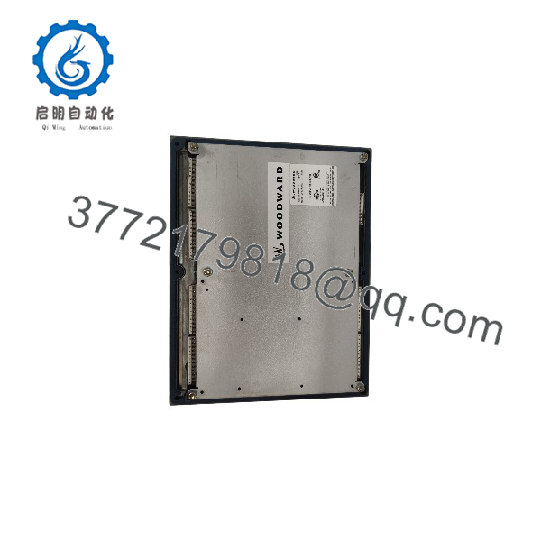
EGCP-2 8406-121
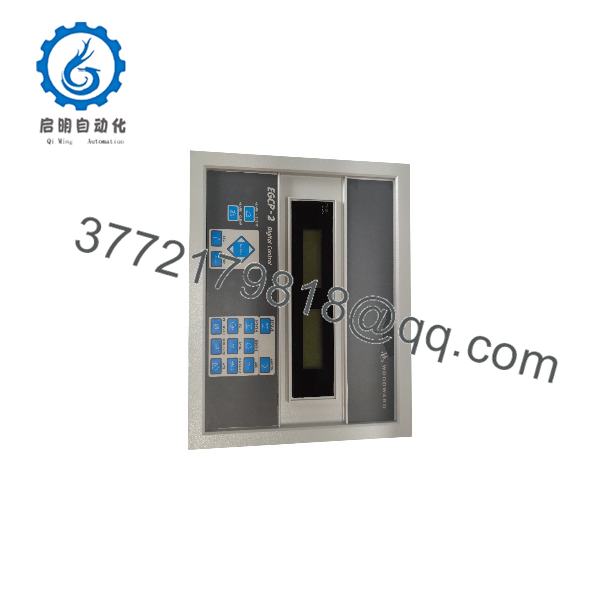
EGCP-2 8406-121
Frequently Asked Questions (FAQ)
Q1: What is the difference between Woodward 8406-121 and 8406-120?
The main difference is the generator PT voltage input range. The 8406-121 accepts 50–150 Vac PT input, while the 8406-120 accepts 150–300 Vac PT input. Verify the generator voltage transformer output before replacement.
Q2: Can the 8406-121 be hot-swapped while the system is running?
No. The is not designed for hot replacement. Remove power before disconnecting wiring. Live replacement can damage the controller or connected equipment.
Q3: Is Woodward 8406-121 obsolete?
The product family is a legacy generator control platform. Many installed systems remain operational, but replacement availability depends on inventory conditions. Before migration, confirm the existing application requirements, wiring, and communication setup.
Q4: Will I lose generator settings when replacing the controller?
Yes, unless configuration data has been documented or transferred. The contains application parameters such as load control, synchronization, protection, and communication settings. Always record settings before removal.
Q5: Why is a surplus Woodward 8406-121 less expensive than a new OEM controller?
Legacy industrial controllers are often available through surplus inventory channels because OEM production cycles have changed. Pricing depends on condition:
- New Original / New Surplus: unused inventory condition
- Refurbished: tested unit with inspection records
- Used: previous service history may vary
Always verify condition documentation before purchase.
Q6: What should be checked before installing a replacement ?
Verify:
- Exact part number: 8406-121
- PT input range
- Firmware compatibility
- Existing communication settings
- CT/PT wiring configuration
- Generator protection parameters
Q7: Does the support Modbus communication?
Yes. The provides serial communication capability through RS-422/RS-485 interfaces and supports Modbus communication for monitoring and configuration applications.



