WhatsApp: +86 16626708626
 Email:
 Phone: +86 16626708626
Description
Key Technical Specifications
| Parameter | Specification |
|---|---|
| Model | MRR1D |
| Product family | Woodward / SEG Electronics HighTECH Line |
| Protection category | Generator rotor protection |
| Mounting | Flush mounting |
| Housing width | 12 TE |
| Rotor insulation measurement range | 1 kΩ to 1 MΩ |
| Rotor insulation test voltage | ±24 V |
| Test frequency | Approximately 0.5 Hz |
| Maximum permitted insulation-measurement input voltage | 600 V DC |
| Excitation-current input | DC current measurement |
| Nominal excitation current | 10 A DC |
| Maximum continuous excitation current | 20 A DC |
| Excitation-current measurement range | Up to 25 A DC |
| Output relays | 5 total; relays 1–4 configurable, relay 5 for self-supervision |
| Serial communication | RS-485 |
| RS-485 slave address | 1–32 |
| Minimum response time | ≤100 ms |
| Return time | ≤30 ms |
| Operating temperature influence range | −20°C to +70°C; stated influence ±2.5% |
| Approximate weight | 1.5 kg |
These values are taken from the MRR1 technical manual. The manual describes the MRR1 protection functions and specifies flush mounting for the “D” variant. Auxiliary supply voltage must be selected from the unit’s nameplate and the applicable general MR-series documentation.
Product Introduction
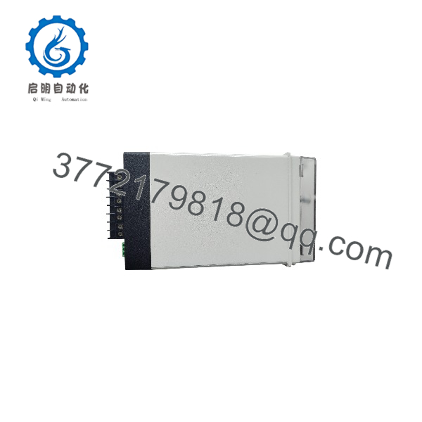
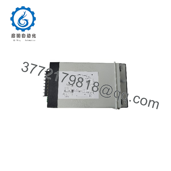
The Woodward MRR1D is a digital protection relay designed to monitor the rotor and excitation system of synchronous generators. It measures rotor insulation resistance to detect earth faults and supervises excitation current for abnormal undercurrent, overcurrent, and ripple conditions. These measurements help identify insulation deterioration and potential rotating-diode failures before they contribute to more serious generator damage. The flush-mounting version is intended for integration into a compatible protection panel.
MRR1D
MRR1D
Installation and Configuration Guide
Stage 1: Verify the Application
- Confirm that the generator is a synchronous machine and that rotor earth-fault and excitation-current monitoring are required.
- Check the full MRR1D nameplate, hardware revision, and auxiliary supply rating.
- Verify that the panel supports the 12-TE flush-mounting format.
- Review the generator excitation schematic, terminal assignments, and existing protection coordination settings.
- Record existing alarm and trip thresholds before replacing a relay.
Stage 2: Prepare for Installation
- Follow the plant’s approved electrical isolation and lockout/tagout procedure.
- Ensure that the generator and excitation circuits are in the required safe maintenance state.
- Identify the relay’s measurement inputs, auxiliary supply, output contacts, blocking input, reset input, and RS-485 connections.
- Label all wiring before disconnecting the existing unit.
Protection-system warning: Do not bypass generator protection or leave trip circuits unintentionally disabled. Any temporary isolation of protection outputs must follow the site’s approved maintenance procedure.
Stage 3: Mount and Wire the Relay
- Install the relay in the specified flush-mounting position.
- Confirm that terminal connections match the MRR1 wiring diagram and the site’s approved drawings.
- Verify the rotor insulation-measurement connections and excitation-current input polarity.
- Wire alarm, trip, and self-supervision outputs according to the protection scheme.
- Connect RS-485 only if remote monitoring or configuration is required.
- Verify the auxiliary supply rating against the nameplate before energizing the relay.
Stage 4: Configure Protection Settings
The MRR1 supports configurable thresholds and time delays for its protection functions.
- Set the rotor insulation-resistance warning threshold and trip threshold.
- Configure the associated alarm and trip delays.
- Set the excitation undercurrent and overcurrent thresholds according to the generator manufacturer’s requirements.
- Configure the excitation-current ripple threshold for rotating-diode fault monitoring.
- Assign the output relays to the appropriate alarm and trip functions.
- Confirm the RS-485 address if the relay is integrated into a serial monitoring network.
Do not copy default settings directly into a live generator protection scheme without checking the generator’s rated excitation current, operating characteristics, and protection coordination requirements.
Stage 5: Commissioning and Functional Testing
- Confirm that the relay starts normally and that its self-supervision function indicates a healthy state.
- Check displayed insulation resistance and excitation-current readings against suitable reference measurements.
- Test output relays and indication functions using the manufacturer’s test procedure.
- Perform secondary-injection testing to verify pickup values and operating delays.
- Verify that alarm and trip signals reach the correct control-system inputs.
- Confirm that any temporary test isolation is removed and that protection is restored before returning the generator to service.
The MRR1 manual describes secondary testing of the insulation-measurement circuit, excitation-current circuit, pickup and dropout values, and trip delays. It also recommends checking the relay functions, settings, and operating times during maintenance.
Frequently Asked Questions
Q1: What is the Woodward MRR1D used for?
It monitors synchronous-generator rotor insulation and excitation current. Its protection functions include rotor earth-fault detection, excitation undercurrent and overcurrent protection, and excitation-current ripple monitoring for potential rotating-diode faults.
Q2: What is the difference between the MRR1D and MRR1A?
The MRR1 ordering information identifies A as the 19-inch rack version and D as the flush-mounting version. Verify the exact mechanical format and ordering information before selecting a replacement.
Q3: Does the MRR1D support RS-485 communication?
Yes. The manual documents an RS-485 serial interface and a configurable slave address from 1 to 32. Confirm the communication protocol and system configuration before integrating the relay into a supervisory network.
Q4: How does the relay detect rotor earth faults?
It applies a low-frequency test voltage to measure insulation resistance between the rotor winding and rotor ground. Separate warning and trip thresholds allow the protection scheme to respond to declining insulation resistance.
Q5: Can the identify rotating rectifier diode problems?
It monitors excitation-current ripple. Abnormal ripple can indicate a fault in the rotating rectifier diodes, while undercurrent and overcurrent supervision help identify other excitation-system abnormalities.
Q6: What should be checked if the relay reports an incorrect measurement?
Verify the measurement wiring, auxiliary supply, current input, configured thresholds, and relevant test circuits. Use the manufacturer’s approved secondary-injection procedure to distinguish an input-circuit problem from a relay fault.
Q7: What should buyers confirm before purchasing a replacement?
Confirm the complete model designation, flush-mounting format, auxiliary supply rating, terminal condition, firmware or hardware revision, and required protection functions. For used or surplus inventory, request actual nameplate photos and available inspection or functional-test records. Stock, condition, and warranty terms should be confirmed with the supplier.