WhatsApp: +86 16626708626
 Email:
 Phone: +86 16626708626
Description
Core Product Summary
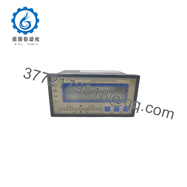
The Woodward SPM-D11 8440-1706B is a microprocessor-based load share synchronizer from the Woodward SPM-D11 series, built in the LSXR package configuration with 100 Vac PT measuring inputs and ../5 A CT measuring inputs. It automatically matches frequency, phase angle and voltage between a generator and a bus, then issues the circuit-breaker closing command — and it combines this synchronizing role with generator power control, power factor control, load/var sharing and built-in generator protection in one flush-mounting panel unit.
The unit works with single-phase or three-phase AC generators and biases Woodward or other compatible speed controls and automatic voltage regulators through discrete raise/lower signals, analog outputs or PWM speed bias. It measures two phases of generator and bus voltage and one phase of generator current, computes true RMS power, and provides two programmable real-power setpoints or an external 0/4–20 mA setpoint. Configuration is possible directly on the front panel or via PC with a dedicated cable and software. The device runs on a 12/24 Vdc supply, carries CE marking and UL/cUL listing, and is designed for panel installation with a 138 × 67 mm cutout.
Key Technical Specifications
| Parameter | Value |
|---|---|
| Product type | Microprocessor-based synchronizing unit, SPM-D11 series, LSXR package |
| Order number | 8440-1706B (SPM-D1115B/LSXR: 100 Vac PT, ../5 A CT, flush mounting) |
| Generator compatibility | Single-phase or three-phase AC generators with Woodward or compatible speed controls and AVRs |
| Synchronizing functions | Frequency, phase and voltage matching; synch-check; synchronization time monitoring; dead-bus (black start) operation |
| Power control | Real power control, true RMS power calculation, two power setpoints or 0/4–20 mA external setpoint, soft unload |
| Power factor control | Yes, with adjustable setpoint |
| Load sharing | Isochronous kW load share line and var share line (terminals 29/30) |
| Generator protection | Over/under voltage (59/27), over/under frequency (81O/U), overload (32), reverse power (32R), under power (32F) |
| Measuring inputs | 2-phase generator voltage, 2-phase bus voltage, 1-phase generator current |
| Voltage measuring range | 50 to 120 Vac (100 Vac rated, version [1]); measuring frequency 40 to 70 Hz |
| Current measuring | ../5 A, linear range 3.0 × I rated, burden < 0.15 VA, transient rating 10 × I rated for 1 s |
| Control outputs (LSXR) | Discrete raise/lower (speed and voltage), freely configurable analog outputs (speed/frequency/real power and voltage/power factor), PWM speed bias 500 Hz |
| Relay outputs | 3 alarm relays, 3 signal relays; isolated, AgCdO contacts, 2.00 Aac @ 250 Vac / 2.00 Adc @ 24 Vdc |
| Discrete inputs | Isolated, 12/24 Vdc (this supply version) |
| Power supply | 12/24 Vdc (9.5 to 32 Vdc), max. 10 W internal consumption |
| Measurement accuracy | Class 1 |
| Display | Two-line LCD with LEDs and push buttons for parameters, alarms and CB status |
| Configuration | Front panel or PC configuration (dedicated cable and software); multi-level password protection; English and German |
| Ambient conditions | −20 to 70 °C, up to 95 % relative humidity, non-condensing |
| Enclosure | APRANORM DIN 43 700 housing, 144 × 72 × 122 mm, approx. 800 g |
| Approvals | CE; UL/cUL listed (voltages up to 300 Vac) |
Engineering Selection Highlights
- Exact package identity matters. 8440-1706B is the LSXR configuration with 100 Vac PT and ../5 A CT inputs; selecting it requires that the site voltage transformers deliver 100 Vac secondaries and current transformers deliver 5 A secondaries, matching the configured measuring range of 50 to 120 Vac.
- Control interface flexibility decides governor/AVR fit. The LSXR package adds freely configurable analog outputs (including ±1 V to ±10 V and 0/4–20 mA ranges) and a 500 Hz PWM speed bias on top of discrete raise/lower outputs, so it can bias analog-input governors and AVRs as well as contact-closing controls — the LSR version cannot.
- Supply version must match the control-voltage scheme. This is the 12/24 Vdc supply version with 12/24 Vdc discrete inputs (9.5 to 32 Vdc operating range); a separate 24 Vdc version exists with 18 to 250 Vac/dc discrete inputs for different plant wiring standards.
- Protection functions reduce relay-panel scope. ANSI-style monitoring for over/under voltage (59/27), over/under frequency (81O/U), overload (32), reverse power (32R) and under power (32F) is integrated, with alarm relays for power limit, reverse/reduced power, overload, and voltage and frequency faults.
- Two operating setpoints or remote setpoint. Two programmable real-power setpoints or an external 0/4–20 mA setpoint input allow base-load or import/export control schemes without an external setpoint unit.
- Load sharing without a separate controller. The integrated isochronous kW load share line and var share line let multiple SPM-D11 units share real and reactive load directly, in single or multiple generator bus configurations.
- Panel protection class is installation-dependent. Front IP42 is achieved only with proper installation; IP54 front protection requires gasket kit P/N 8923-1037, relevant for dusty or damp cabinets.
SPM-D11 8440-1706B
SPM-D11 8440-1706B
System Compatibility & Integration Requirements
| Item / Dependency | Verified Compatibility or Requirement | Practical Note |
|---|---|---|
| Speed control / governor | Woodward or other compatible speed controls | Bias via discrete raise/lower, analog output or 500 Hz PWM speed signal (LSXR) |
| Voltage regulator (AVR) | Woodward or other compatible AVRs | Bias via discrete raise/lower or configurable analog output |
| Measuring transformers | 100 Vac PT secondaries, ../5 A CT secondaries | Measuring range 50 to 120 Vac; CT secondary must match the ordered version |
| Bus reference | 2-phase bus voltage measuring, synchronization reference at terminals 20/21 | Reference point terminal 0 for star systems or PT neutral |
| Load sharing interconnection | Load share line and var share line, terminals 29/30 | Enables isochronous kW and var sharing between SPM-D11 units |
| External setpoint | 0/4–20 mA real power setpoint input | Alternative to the two internal power setpoints |
| Configuration interface | Front-panel configuration or PC configuration socket on the side of the unit | PC configuration requires the dedicated cable and software (DPC) |
| Power supply | 12/24 Vdc version, 9.5 to 32 Vdc | Check the data plate before connection; incorrect supply can destroy the unit |
| Circuit breaker | Control of one generator circuit breaker | CB close/open commands and CB status feedback wired to relay outputs and discrete inputs |
Dimensions, Mounting & Connection Notes
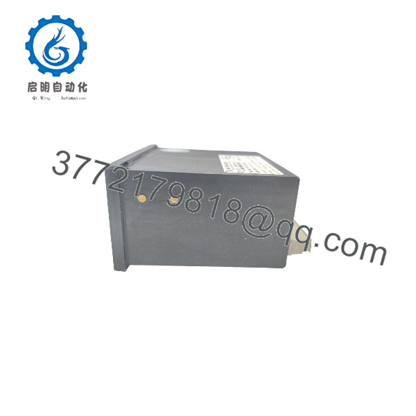
- Dimensions: 144 × 72 × 122 mm (H × W × D), weight approx. 800 g.
- Mounting: Flush panel mounting in an APRANORM DIN 43 700 standard housing; panel cutout 138 (+1.0) × 67 (+0.7) mm.
- Wiring: Screw or plug terminals (depending on connector) for 1.5 mm² or 2.5 mm² conductors; the AWG conversion chart in the installation chapter covers wire sizing.
- Protection: Front IP42 and rear IP21 with proper installation; IP54 front protection with gasket kit P/N 8923-1037.
- Reference point: Terminal 0 is the measuring reference (neutral point or PT neutral terminal); with three-conductor delta systems this terminal must not be connected.
- CT grounding: Current transformer secondaries are generally to be grounded on one side.
- Suppressors: Inductive devices connected to the system (operating current coils, undervoltage tripping units, auxiliary contacts) must be connected to a suitable interference suppressor.
- Isolation switch: A circuit breaker for the control supply must be located near the unit and identified as its isolating switch.
- ESD handling: Standard electrostatic discharge precautions apply; avoid plastic, vinyl and Styrofoam materials around the unit and PCB.
Detailed Product Overview
The SPM-D11 series answers a practical question in generator control: synchronizing, load control and generator protection are usually three separate pieces of hardware, but many installations need all three in one panel location. Woodward’s answer is a single microprocessor-based panel unit that spans the full sequence — black start, speed and voltage matching, synch-check, breaker closing, load sharing and protection.
The 8440-1706B is the LSXR variant of this series. Its identity is encoded in the model designation: 100 Vac PT measuring inputs (digit 1), ../5 A CT measuring inputs (digit 5), flush mounting (B), and the LSXR function package. What distinguishes LSXR from the basic LSR package is the controller output structure. LSR units can only raise and lower speed and voltage through discrete (relay-contact) signals. The LSXR package adds freely configurable analog outputs — covering ranges such as ±1 V, ±3 V, 0 to 5 V, 0.5 to 4.5 V, ±5 V, ±10 V, 0 to 20 mA and ±20 mA — plus a 500 Hz PWM speed bias. This matters at selection time: if the governor accepts a ±10 V speed bias or the AVR accepts a current-mode voltage bias, the LSXR package is the variant that can drive it directly, and discrete raise/lower remains available for controls without analog inputs.
The measurement side is built for two-phase voltage sensing of both generator and bus, and single-phase current sensing, with a 40 to 70 Hz measuring window and Class 1 accuracy. True RMS power calculation makes the real-power controller less sensitive to distorted waveforms than average-responding measurement, which is a meaningful advantage on modern generator loads with harmonic content. The current input sustains 10 × I rated for one second, so standard CT secondary transients during faults do not damage the measuring circuit.
During synchronization, the unit can operate in phase-matching mode or in slip-frequency synchronization, and a synchronization time monitoring function supervises how long the process takes. Synch-check and the selectable SPM-A-style operating modes (run, check, permissive) give the commissioning engineer graduated control over how much authority the automatic synchronizer has over the breaker. Dead-bus operation allows the breaker to close without synchronization when the bus is unenergized, which is the normal black-start path.
Once the breaker is closed, the SPM-D11 becomes the load controller. Real power is controlled to one of two programmable setpoints or to an external 0/4–20 mA setpoint from a plant control system. Power factor can be held to an adjustable setpoint using the voltage bias output. On multi-unit buses, the load share line and var share line distribute kW and kvar between units without a central controller. Before opening the breaker, the soft-unload function ramps the generator load down, protecting the prime mover from step load rejection.
The protection set covers the failure modes most likely in paralleled operation: over/under voltage (59/27), over/under frequency (81O/U), overload (32), reverse power (32R) and under power (32F). Alarm and signal relays report these conditions; all relays are open when the unit is de-energized, so wiring schemes can rely on a defined de-energized state.
Configuration deserves planning. Parameters can be set directly on the front panel — a two-line LCD with LEDs for CB status and alarms — or via a PC using the configuration socket on the side of the unit, which requires a dedicated cable and software. Multi-level password protection restricts parameter access on commissioned units. The manual for this unit applies from software version 6.3xx, and the data plate must be checked before wiring the power supply, because SPM-D11 units exist in two supply voltage versions and an incorrect supply can destroy the unit.
Installation constraints are modest: a 138 × 67 mm panel cutout, 1.5 or 2.5 mm² terminal wiring, −20 to 70 °C ambient and non-condensing humidity up to 95 %. Front protection is IP42 as standard, upgrading to IP54 with gasket kit P/N 8923-1037. CE marking and UL/cUL listing up to 300 Vac support use in both European and North American panel builds.
Applications & System Role
The SPM-D11 8440-1706B sits between the generator measurement circuits and the prime-mover/voltage-control chain in a power generation switchboard. It continuously measures generator and bus voltage, generator current and the synchronization reference, and drives the speed control and AVR so that the generator reaches synchronism, then closes the generator circuit breaker.
After paralleling, it operates as a load controller: it holds the programmed real-power setpoint, regulates power factor, shares kW and kvar between multiple generators on the same bus via the load share and var share lines, and performs soft unloading before opening the breaker. Its integrated monitoring functions (voltage, frequency, overload, reverse power) provide generator protection that would otherwise require discrete protective relays in simple genset installations.
Typical fit scenarios documented for the series include single-unit operation without paralleling, multiple-unit operation with load sharing, and single or multiple units paralleled to a utility mains. The unit is designed for one- or three-phase AC generators, so it applies to both small single-phase gensets and three-phase generating sets equipped with compatible governors and voltage regulators.
FAQ
What is the Woodward SPM-D11 8440-1706B?
It is a microprocessor-based load share synchronizer in the Woodward SPM-D11 series, delivered in the LSXR package with 100 Vac PT measuring inputs, ../5 A CT measuring inputs and flush mounting, designed for single- and three-phase AC generators.
What does the SPM-D11 8440-1706B do?
It automatically matches generator frequency, phase angle and voltage to the bus, issues the circuit-breaker closing command, then controls real power, power factor, and kW/kvar load sharing, while providing integrated generator protection.
Which controllers can it work with?
It biases Woodward or other compatible speed controls and automatic voltage regulators, using discrete raise/lower signals, configurable analog outputs or a 500 Hz PWM speed bias.
What are its power supply requirements?
This version operates on a 12/24 Vdc supply (9.5 to 32 Vdc) with 12/24 Vdc discrete inputs and a maximum internal consumption of 10 W; the data plate should be checked before connection because two supply voltage versions exist.
What voltage and current measuring inputs does it need?
Voltage transformers with 100 Vac secondaries (measuring range 50 to 120 Vac) and current transformers with ../5 A secondaries; the CT secondary rating must match the ordered version.
How is the unit configured?
Directly via the front panel using the LCD and push buttons, or via a PC through the configuration socket on the side of the unit, which requires the dedicated cable and configuration software; parameter access is password protected.
What generator protection functions are built in?
Over/under voltage (59/27), over/under frequency (81O/U), overload (32), reverse power (32R) and under power (32F), with corresponding alarm and signal relays.
How is it mounted, and what environmental limits apply?
It flush-mounts in a 138 × 67 mm panel cutout (housing 144 × 72 × 122 mm), weighs approximately 800 g, and operates from −20 to 70 °C at up to 95 % relative humidity, non-condensing.