
 WhatsApp: +86 16626708626
 Email:
  Phone: +86 16626708626
Description
- Key Technical Specifications
| Parameter | Specification |
| Part / Model Number | XVME-244 |
| Manufacturer | Xycom Automation |
| Bus Standard | VMEbus (6U Form Factor, IEEE-1014 compliant, A24/A16, D16/D08) |
| Digital Channels | 64 Digital Input/Output Lines (Configurable in 8-line ports) |
| I/O Signal Levels | TTL / CMOS compatible (5V nominal logic) |
| Data Buffer / Storage | Onboard register-mapped I/O ports with interrupt generation |
| Interrupt Capability | VMEbus interrupt requester (programmable level IRQ1–IRQ7) |
| Operating Temperature | 0°C to +65°C (32°F to 149°F) |
| Form Factor / Size | 6U VMEbus single-slot card |
| Weight | ~0.50 kg (1.10 lbs) |
- Product Introduction
The Xycom XVME-244 is a high-density, 64-channel digital input/output module built on the standard 6U VMEbus architecture. Originally developed by Xycom for industrial automation, automotive test stands, and military simulation racks, the XVME-244 allows host VME processors to sense contact closures, monitor status signals, and actuate solid-state relays or indicator banks across 64 discrete lines.
Organized into eight 8-bit software-configurable ports, the XVME-244 features programmable maskable interrupt generation, allowing high-priority state changes on input lines to immediately trigger CPU interrupts. Built with rugged industrial-grade components and transient protection, the XVME-244 provides deterministic digital control in demanding real-time environments.
- Troubleshooting Quick Reference
| Symptom | Possible Cause | Relevance to this Part | Quick Check Method | Recommendation |
| Host VME CPU generates Bus Error (BERR) | Incorrect base address DIP switch setting or VME slot address collision | ✅ High | Check DIP switch settings on board against system VME memory map | Align address switches with system configuration. Re-seat card in 6U rack slot. |
| Digital input channel fails to update register | TTL driver failure on input port or missing ground reference | ✅ High | Apply 5V test signal directly to P2/front connector pin; read port register | Verify field sensor signal levels. Replace buffer IC or board if port stays logic LOW. |
| Output channel stuck in HIGH/LOW state | Blown output driver chip (e.g., 74ACT/74F buffer) due to overcurrent | ✅ High | Measure voltage on output pin with load disconnected | Inspect external field wiring for shorts. Replace XVME-244 module if driver IC is damaged. |
| VME Interrupts not registering on host CPU | Incorrect IRQ jumper selection or interrupt vector mismatch | ✅ High | Inspect onboard IRQ level jumpers and vector control register settings | Re-configure IRQ jumper block (IRQ1–7) to match software interrupt handler configuration. |
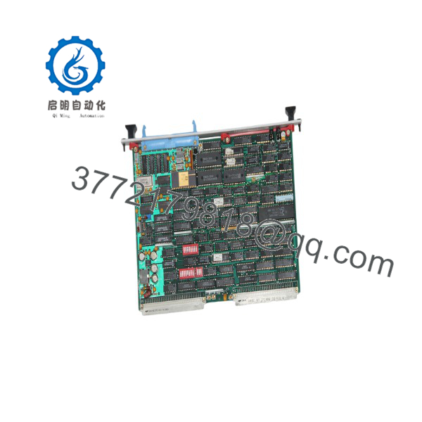
XVME-244
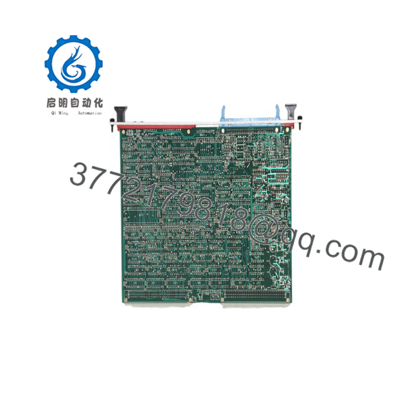
XVME-244
- Frequently Asked Questions (FAQ)
Q: Is the Xycom still actively manufactured?
A: No. The and the broader XVME product line have been discontinued by Xycom (GE Automation). Replacement cards are supplied via certified refurbished stock or high-quality new surplus.
Q: How are the 64 digital channels configured on the ?
A: The 64 channels are grouped into eight 8-bit ports. Each port can be independently configured via software or DIP/jumper settings as either inputs, outputs, or bi-directional data lines.
Q: What signal levels does the support natively?
A: Standard logic levels are TTL/CMOS compatible (0–5 VDC). For higher voltage field signals (e.g., 24 VDC or 120 VAC), external optical isolation rack panels (such as Xycom XVME-950 series breakout racks) are connected via ribbon cable.
Q: Does the require external DC power inputs?
A: No. Logic power is drawn directly from the VMEbus backplane (+5 VDC rail).
Q: How are surplus or refurbished Xycom modules verified prior to shipment?
A: Each module passes a 5-step SOP quality inspection: VME connector pin inspection, installation into a 6U VME test chassis, 64-channel loopback toggling under electrical load, multi-hour thermal burn-in, and ESD static-shield packaging prior to dispatch.



