
 WhatsApp: +86 16626708626
 Email:
  Phone: +86 16626708626
Description
Key Technical Specifications
| Parameter | Value |
|---|---|
| Manufacturer | Yaskawa |
| Model Number | CIMR-VU2A0020FAA |
| Product Family | V1000 compact current-vector AC drive |
| Product Type | Variable frequency drive / variable-speed drive / AC inverter |
| Input Voltage | 200–240 V AC, three phase |
| Input Frequency | 50/60 Hz |
| Input Current | 24.0 A / 18.9 A, as listed for the model |
| Output Voltage | 0–240 V AC, three phase; proportional to input voltage |
| Output Frequency | 0–400 Hz |
| Normal-Duty Output Rating | 19.6 A; 5 HP |
| Heavy-Duty Output Rating | 17.5 A; 5 HP |
| Motor Power Rating | 5 HP / 3.7 kW |
| Control Method | Open-loop current vector control |
| Motor Types | Induction motor and permanent-magnet motor support |
| Enclosure Classification | NEMA 1 / Type 1 |
| Ingress Protection | IP20 |
| Standard Communications | RS-422/485 Modbus, up to 115 kbps |
| Optional Networks | DeviceNet, EtherCAT, EtherNet/IP, MECHATROLINK-II, MECHATROLINK-III, Modbus TCP/IP, PROFIBUS-DP, and PROFINET |
| Dimensions, H × W × D | 6.02 × 5.51 × 5.63 in. |
| Weight | 5.7 lb / approximately 2.6 kg |
| Dynamic-Braking Resistor, 10% Duty | Yaskawa USR000025; 40 Ω; 846 W; one resistor required |
| Replacement Requirement | Match full model number, nameplate spec number, duty rating, input supply, motor FLA, control wiring, option cards, and parameter backup |
Yaskawa identifies CIMR-VU2A0020FAA as a V1000 240 V-class, three-phase, NEMA 1 drive rated at 19.6 A normal duty and 17.5 A heavy duty, both at 5 HP. The V1000 family supports 0–400 Hz output and open-loop current vector control.
Product Introduction
Yaskawa CIMR-VU2A0020FAA is a V1000 compact current-vector variable frequency drive for three-phase AC motor control. It accepts 200–240 V AC, three-phase input and provides adjustable three-phase output for 5 HP / 3.7 kW motors in pumps, fans, conveyors, mixers, compressors, machine tools, and general industrial equipment.
The drive provides 19.6 A normal-duty output or 17.5 A heavy-duty output, depending on the application rating. It includes standard RS-422/485 Modbus communication and supports multiple optional industrial networks. Confirm the motor full-load current, duty type, braking needs, option cards, and saved parameters before replacing the drive.
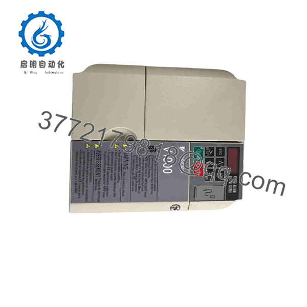
CIMR-VU2A0020FAA
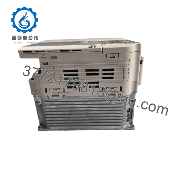
CIMR-VU2A0020FAA
Troubleshooting Quick Reference
| Symptom | Possible Cause | Relevance to This Part | Quick Check Method | Recommendation |
|---|---|---|---|---|
| Drive display is completely dark | Missing input power, open disconnect, blown fuse, tripped breaker, failed control power, damaged drive | ✅ Medium | Measure phase-to-phase voltage at input terminals R/L1, S/L2, and T/L3 using correctly rated equipment; verify upstream disconnect, fuses, and breaker | Confirm correct 200–240 V three-phase input before replacing the drive. |
| Drive powers up but will not run | Run command missing, digital-input programming wrong, local/remote selection issue, safety circuit open, speed reference missing | ✅ High | Review the keypad status and monitor parameters; verify run-command source, frequency-reference source, digital input state, and any external permissive circuit | Check parameters and control wiring before replacing the VFD. Most no-run calls are command-source issues. |
| Motor runs in the wrong direction | Motor leads reversed, reverse command active, parameter configuration incorrect | ❌ Low | Stop and isolate the drive; verify output lead order U/T1, V/T2, W/T3 and command logic; perform a low-speed jog test | Swap any two motor leads only with power removed, or correct the direction command/parameter. |
| Overcurrent fault during acceleration | Acceleration time too short, mechanical jam, motor cable short, incorrect motor data, motor too large, excessive load inertia | ✅ High | Disconnect the motor and insulation-test cable/motor as permitted; check mechanical load; compare motor nameplate FLA to 17.5 A HD or 19.6 A ND rating; lengthen acceleration time | Correct the mechanical or parameter cause. Replace the drive only if it faults unloaded with verified correct parameters. |
| Overvoltage fault during deceleration | Deceleration too fast, high-inertia load, regenerative energy, braking resistor missing or incorrectly sized | ✅ High | Review fault history; increase deceleration time; check braking-transistor/resistor wiring; compare installed resistor to approved Yaskawa selection | Use an approved braking resistor or longer deceleration ramp. For 10% duty, Yaskawa lists USR000025, 40 Ω, 846 W for this drive. |
| Motor overheats at low speed | Motor cooling inadequate, V/Hz or vector settings wrong, continuous torque demand too high, motor undersized | ❌ Low | Measure motor current with a clamp meter; compare to motor nameplate; inspect shaft-mounted fan operation and motor temperature | Use a separately powered blower or derate the motor at low speed. Do not assume the drive has failed. |
| Drive trips on ground fault or short circuit | Damaged motor cable, moisture in motor junction box, failed motor winding, output wiring error | ✅ High | Lock out power; disconnect motor leads at the drive; insulation-test motor and cable according to manufacturer procedure; inspect U/V/W conductors | Repair cable or motor insulation before connecting a replacement drive. Never megger through the VFD output terminals. |
| Communications timeout | Wrong Modbus address, baud rate, parity, RS-485 polarity, termination, parameter settings, damaged cable | ✅ High | Verify RS-422/485 wiring, A/B polarity, shield grounding, address, baud rate, parity, and stop bits; compare against PLC or HMI settings | Correct network settings and cable wiring first. Standard V1000 communications use RS-422/485 Modbus. |
| Replacement drive trips immediately after commissioning | Parameters not restored, motor data incorrect, wrong control mode, option card mismatch, braking wiring error | ✅ High | Restore the saved parameter file; compare every critical parameter to the removed drive; check control terminals and installed option cards | Do not copy parameters blindly across unlike revisions. Verify motor data, command source, I/O assignments, and safety logic. |
| Drive runs hot or fan alarm occurs | Blocked airflow, failed cooling fan, high ambient temperature, undersized enclosure, excessive carrier frequency | ✅ High | Inspect heatsink and air passages; verify fan operation; check cabinet temperature; measure output current and review carrier-frequency parameter | Clean airflow paths and replace the fan if needed. Yaskawa lists a 24 V DC cooling fan as a service part for this model. |
❗ Input-voltage warning: This is a 200–240 V-class, three-phase input drive. Do not connect it to 380–480 V AC. That mistake can destroy the rectifier and DC bus immediately. Verify phase-to-phase voltage at the disconnect and at R/L1, S/L2, and T/L3 before energizing.
❗ Duty-rating warning: The 5 HP label does not tell the full story. This drive is rated 19.6 A normal duty and 17.5 A heavy duty. For constant-torque loads such as conveyors, mixers, positive-displacement pumps, or compressors, use the heavy-duty current rating unless the application is documented otherwise.
❗ Parameter backup warning: Photograph and export the old drive’s parameters before removal. Record motor nameplate data, control mode, acceleration/deceleration times, minimum/maximum frequency, digital-input assignments, analog scaling, fault-reset logic, and network settings. I have seen a drive replacement take two days because the new drive started with factory defaults and the original had nonstandard terminal assignments.
❗ Motor insulation warning: Never insulation-test from U/T1, V/T2, or W/T3 to ground with the drive connected. Disconnect the motor leads first. A megohmmeter can damage VFD output transistors and gate circuitry.
❗ Braking warning: A high-inertia fan, centrifuge, conveyor, or fast-stop machine can regenerate energy during deceleration and cause an overvoltage trip. Do not lower deceleration time until braking capacity has been calculated. For the listed 10% duty braking configuration, Yaskawa specifies one 40 Ω, 846 W USR000025 resistor.
❗ ESD warning: Use a grounded wrist strap whenever handling option cards, control boards, or the keypad connector. I have watched a technician replace a good VFD control board after setting it on a dry cardboard box; it powered up but lost its RS-485 port during commissioning. Use ESD protection.
Keep these checks in mind and you will save yourself 90% of typical rework time. If you need technical support, send photos of the complete nameplate, fault code, parameter backup, motor nameplate, input-voltage readings, control-terminal wiring, installed option cards, braking resistor label, and PLC/HMI communications settings.
Frequently Asked Questions
What is the Yaskawa CIMR-VU2A0020FAA?
Yaskawa CIMR-VU2A0020FAA is a V1000 variable frequency drive for 200–240 V AC three-phase motor applications. It is rated for 5 HP and provides 19.6 A normal-duty or 17.5 A heavy-duty output. It is a NEMA 1 enclosure model.
Is this drive suitable for a 5 HP motor?
Yes, provided the application and motor current remain within the drive’s applicable duty rating. The model is rated at 5 HP in both normal-duty and heavy-duty tables, but current rating determines whether it is suitable for the real load: 19.6 A normal duty and 17.5 A heavy duty.
Check the motor nameplate full-load amps, not horsepower alone. If the motor FLA exceeds the relevant drive output-current rating, select a larger drive.
Can I use CIMR-VU2A0020FAA on 480 V power?
No. is a 200–240 V-class three-phase drive. Connecting it to 480 V supply can cause immediate and severe internal damage. Use a correctly rated 480 V-class or another suitable drive for a 380–480 V system.
Does the drive support Modbus communication?
Yes. The has standard RS-422/485 Modbus communications at up to 115 kbps. The family also supports optional network interfaces including DeviceNet, EtherCAT, EtherNet/IP, MECHATROLINK-II, MECHATROLINK-III, Modbus TCP/IP, PROFIBUS-DP, and PROFINET.
For an existing PLC connection, confirm whether the installed drive uses the onboard RS-485 port or an optional communication card. A replacement with no matching option card will not restore network communications by itself.
Can I copy parameters from my old to a replacement?
Usually, but only after verification. Parameter copying is the right starting point for a like-for-like replacement, yet it can create trouble if firmware revisions, installed option cards, motor data, or I/O wiring differ. Back up the original parameters first, retain screenshots or a printed list of critical settings, then load and review the configuration in a controlled maintenance window.
At minimum, verify:
- Motor rated voltage, current, frequency, RPM, and power
- Control mode and autotuning results
- Run-command and frequency-reference source
- Digital-input and analog-input assignments
- Acceleration and deceleration settings
- Maximum frequency and speed limits
- Carrier frequency and motor protection settings
- Communications address and serial settings
- Fault response, external interlocks, and reset behavior
Does this support a dynamic-braking resistor?
Yes. Yaskawa lists an optional 10% duty dynamic-braking resistor for this model: USR000025, one required, 40 Ω, 846 W, with approximately 111% peak braking torque shown in the selection table. Use only an approved braking arrangement and verify actual duty cycle, deceleration requirement, load inertia, resistor thermal rating, and enclosure ventilation.
Do not use an arbitrary resistor value. Too little resistance can overload the braking transistor; too little wattage can overheat the resistor or create a fire hazard.
Is obsolete, and why is New Surplus stock cheaper?
The is an established drive family and this exact model may be found through current distribution, surplus inventory, or refurbished stock depending on region and lifecycle status. Yaskawa still provides a spare-parts listing for , but that listing also marks certain individual internal service parts as no longer available.
New Surplus stock can cost less because it comes from unused project material, cancelled panel builds, distributor overstock, or warehouse spares. Before ordering, request:
- Actual photos of the complete
nameplate and spec number - Confirmation of Factory Sealed, New Original / New Surplus, or Refurbished (tested) condition
- Input class, enclosure type, and installed option-card photos
- Manufacturing date, firmware revision, and keypad condition where available
- Warranty duration, return terms, verified quantity, and dispatch lead time
What testing should a supplier complete before shipment?
A supplier should complete a documented test sequence:
- Inbound inspection and traceability: Verify OEM labels, spec number, serial number, packaging, seals, and source documents. Inspect the enclosure, keypad, terminals, control board, fan, and option slots for corrosion, heat discoloration, damaged terminals, rework marks, cracked plastic, or altered labels.
- Power-on inspection: Apply regulated 200–240 V AC three-phase power through appropriate protection. Confirm normal keypad startup, absence of fault codes, stable DC-bus behavior, fan operation, and no abnormal noise or heat.
- Motor-run test: Connect a correctly sized three-phase test motor. Run forward and reverse at low, medium, and rated speed. Verify output-frequency stability, motor-current behavior, acceleration/deceleration response, and fault-free operation.
- I/O test: Verify digital inputs, run/stop command, fault reset, analog reference scaling, relay outputs, and analog monitor output against documented terminal assignments.
- Communications test: Test onboard RS-422/485 Modbus using a known-good host. Confirm address, baud rate, parity, read/write behavior, and stable communications. Test any installed option card separately.
- Braking and protection test: Where bench equipment permits, verify controlled deceleration and proper operation of the braking circuit with an approved resistor. Confirm protective behavior for controlled open-loop, overcurrent, and thermal conditions; do not create uncontrolled faults.
- Load and thermal test: Run the drive under representative current for more than 24 hours where suitable equipment is available. Monitor output current, temperature, fan function, fault history, and communications stability.
- Final QC and packaging: Obtain QC inspector sign-off, document firmware and parameter state, fit terminal covers, protect connector and option-card interfaces, use anti-static packaging for electronic accessories, and ship in heavy-duty corrugated packaging. Test photos and a dated test report should be available upon request.



