
 WhatsApp: +86 16626708626
 Email:
  Phone: +86 16626708626
Description
Key Technical Specifications
| Parameter | Specification Value |
| Manufacturer | Yaskawa Electric |
| Part Number | JUSP-RA05 |
| Drive Compatibility | Yaskawa Sigma-II / Sigma-III Servopacks |
| Nominal Resistance | 50 Ω |
| Continuous Power Rating | 120 W |
| Peak Absorption Capacity | 1.2 kW (short duration) |
| Thermal Protection | Integrated thermal switch contact (normally closed) |
| Cooling Method | Natural convection / chassis heat sink |
| Mounting Style | Direct chassis / panel bracket mounting |
| Operating Temperature | −10 to +55 °C (+14 to +131 °F) |
| Enclosure Rating | IP20 panel-mount standard |
Product Introduction & Supply Chain Strategy
The Yaskawa JUSP-RA05 is an external regenerative resistor unit designed to connect directly with Yaskawa Servopack drives. It safely dissipates excess kinetic energy returned by high-inertia servo motors during rapid deceleration phases, preventing over-voltage trips on the drive’s main DC bus.
Sourcing the JUSP-RA05 as New Surplus ensures direct mechanical and electrical compatibility without risking the internal thermal degradation common to used braking units. Genuine New Surplus stock eliminates the danger of compromised wire-wound element insulation, preventing unexpected over-voltage faults and protecting high-throughput automated lines from costly, unplanned stops.
Installation & Configuration Guide
Stage 1: Pre-Installation (Prep & Safety)
- Execute complete Lock-Out/Tag-Out (LOTO) on the servo system main breaker and wait at least 10 minutes for DC bus capacitors to fully discharge.
- Check the drive DC bus voltage with a multimeter to verify it has dropped below 50 V DC before approaching terminal connections.
- Photograph existing wiring connections to terminal block B1/B2 (or P/B) and thermal protection interlock lines on the original resistor module.
Stage 2: Removal
- Disconnect the main power lines from the resistor terminals using an insulated screwdriver.
- Disconnect the thermal switch leads tied into the system safety fault circuit.
- Unbolt the mounting screws securing the JUSP-RA05 bracket to the panel backplate and carefully remove the unit.
Stage 3: Installation (Clone & Seat)
- Mount the new JUSP-RA05 vertically onto the panel surface, maintaining at least 100 mm (4 inches) of clearance around the heat sink fins for proper natural convection.
- Tighten mounting hardware to 1.2 N·m torque to ensure structural grounding and heat dissipation.
- Connect the power leads to terminals B1 and B2 on the Servopack drive and wire the thermal switch contacts into the drive’s emergency stop circuit.
Stage 4: Power-On & Testing
- Verify terminal connection tightness and confirm no loose strands or grounded wires are present.
- Apply control power and verify that the drive parameters for external regenerative resistor usage (e.g., parameter Pn600 / Pn001 depending on drive model) are set to enable external unit processing.
- Perform a low-speed deceleration trial while monitoring drive DC bus voltage to ensure smooth energy dissipation without over-voltage alarms.
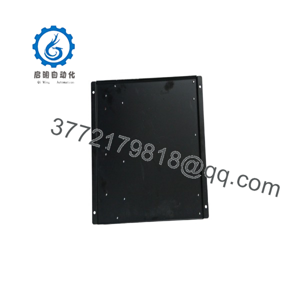
JUSP-RA05
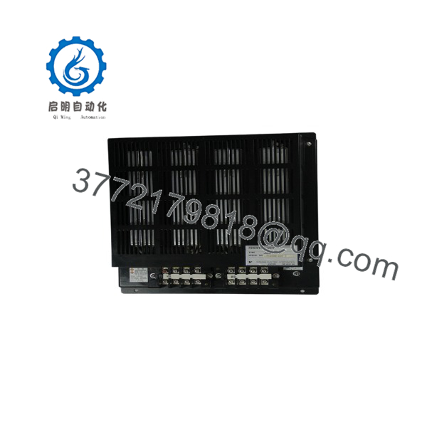
JUSP-RA05
Firmware/Software Versions & Upgrade Notes
- Recommended Parameter Setup: Ensure Servopack parameter configuration explicitly matches the 50 Ω / 120 W rating of the JUSP-RA05 unit.
- Compatibility Notes: The is fully cross-compatible with multiple Yaskawa drive generations requiring 50 Ω external absorption. Ensure the total continuous power rating of 120 W matches your duty cycle requirements to avoid thermal cutouts.
- Upgrade/Downgrade Risks: Incorrect parameter selection in the host drive (e.g., leaving the drive configured for internal built-in resistor capacity while using an external unit) will disable proper thermal protection, risking drive bridge failure during heavy braking cycles.
Frequently Asked Questions (FAQ)
Why is this New Surplus unit priced higher than used braking resistors available online?
Used or refurbished braking units frequently suffer from degraded ceramic insulation and fatigued thermal switches caused by cyclic heating. Our Yaskawa stock consists strictly of verified New Surplus—original, uninstalled hardware held in clean storage. Investing in New Surplus guarantees 100% thermal capacity and avoids drive trips that cause thousands of dollars in lost production time.
Is this an original Yaskawa factory component?
Yes. Every unit is guaranteed to be an authentic Yaskawa OEM module. It is not second-hand surplus, repaired stock, or an aftermarket copy, and it undergoes comprehensive visual and resistance verification prior to shipment.
What is the current manufacturing lifecycle status for the ?
The is an EOL (End-of-Life) accessory unit as drive families transition to newer product lines. Obtaining replacement units directly from factory distribution can involve lengthy lead times. Holding 1-2 spare units on-site acts as a vital buffer stock strategy to prevent extended machine downtime.
Can the be installed without connecting the thermal switch?
No. Operating the unit without wiring its integrated thermal switch into the drive safety loop exposes the resistor to burnout during continuous overload conditions. Always interlock the thermal contact with the drive’s main contactor control logic.
How do I confirm if my drive requires an external unit?
If your drive experiences main circuit over-voltage alarms (such as A.400 or A.410 on Yaskawa drives) during motor deceleration, your current regeneration capacity is insufficient. Adding or replacing the provides the required external capacity to handle high-inertia stops.
What warranty is provided with this New Surplus resistor unit?
This New Surplus Yaskawa unit comes backed by a full 1-year replacement warranty and includes a verified pre-shipment quality inspection report.



