
 WhatsApp: +86 16626708626
 Email:
 Phone: +86 16626708626
Description
Core Product Summary
The Yaskawa SARCR-XFB01A01 is associated with the SARCR-XFB01 fieldbus interface board used in Motoman robot controller systems. The board provides an interface between the robot controller and an industrial fieldbus network through a compatible Anybus communication module. Its role is to exchange control and status data between the robot controller and external automation equipment, such as a PLC.
The interface assembly includes a 24 V DC power connection, a status indicator, configuration switches, and a communication connector. Network configuration depends on the installed Anybus module, which determines the supported fieldbus type and its associated settings. Before selecting this board, check the complete part number, installed communication module, and robot controller model. The A01 suffix should be retained when identifying the required assembly.
Key Technical Specifications
| Parameter | Specification |
|---|---|
| Manufacturer | Yaskawa |
| Model designation | SARCR-XFB01A01 |
| Board family | SARCR-XFB01 |
| Product type | Fieldbus interface board |
| Application | Motoman robot controller communication |
| Interface architecture | Carrier board with an Anybus communication module |
| Power connection | 24 V DC |
| Status indication | LED |
| Configuration elements | DIP switches and station-address setting |
| Communication connector | Depends on the installed fieldbus module |
| Network configuration | Depends on the installed Anybus module |
Detailed Product Overview
Role in robot controller integration
The SARCR-XFB01 fieldbus interface board provides a communication path between a Motoman robot controller and external industrial automation equipment. Rather than replacing the robot controller’s internal control functions, it supports data exchange over a configured fieldbus network.
In an integrated production cell, this interface can form part of the connection between robot control and a supervisory PLC. The exchanged data may be used for coordinating machine states, process commands, and external control signals, subject to the configured network and robot-controller application.
Modular communication architecture
The XFB01 architecture uses a carrier board together with an Anybus fieldbus module. This distinction matters when identifying the correct hardware: the carrier-board designation alone does not establish which network protocol is installed.
The documented XFB01 architecture supports different fieldbus implementations through corresponding Anybus modules. Depending on the installed module, network setup may involve protocol-specific configuration, communication parameters, and device-description files. The communication connector and network commissioning procedure must therefore be matched to the actual module.
Configuration and diagnostics
The carrier board provides configuration switches for settings such as station identification and I/O data size. It also includes a status LED and a diagnostic connection used for board configuration or firmware-related service procedures.
Correct switch settings are important because the robot controller’s configured I/O data length must agree with the fieldbus configuration. A mismatch can prevent the intended data exchange even when the physical connection is correct.
Configuration changes should be performed with the controller powered down where required by the installation instructions. Electrostatic-discharge precautions are also necessary when handling the interface hardware.
Replacement and procurement considerations
When sourcing the SARCR-XFB01A01, compare the full designation on the installed board and identify the fitted Anybus module. Check the robot controller family, network protocol, connector arrangement, and required I/O data size before choosing a replacement.
A carrier board intended for one fieldbus implementation should not be assumed to provide the same network functionality as a board fitted with another communication module. The installed hardware and the controller’s network configuration must be considered together.
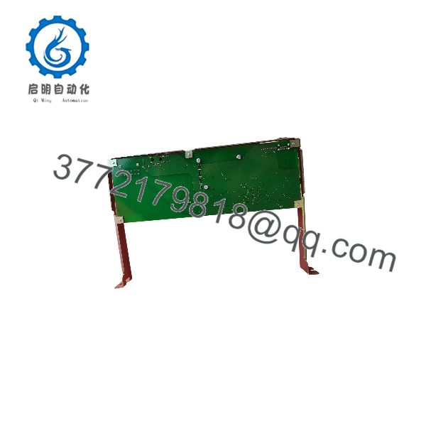
SARCR-XFB01A01
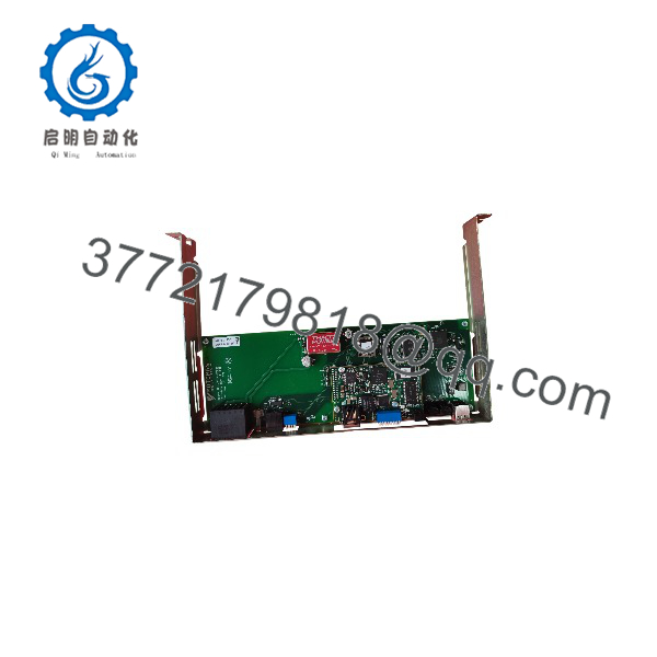
SARCR-XFB01A01
System Compatibility & Integration Requirements
| Item / Dependency | Verified Requirement | Practical Note |
|---|---|---|
| Robot controller | Motoman NX100 is documented for the SARCR-XFB01 architecture | Confirm the actual controller model and installed hardware configuration. |
| Communication module | Compatible Anybus module | Identify the fitted module before determining network compatibility. |
| Power supply | 24 V DC connection | Confirm the connection and supply arrangement against the installed board documentation. |
| Network protocol | Determined by the installed Anybus module | Match the protocol to the external PLC or network master. |
| I/O data size | Configurable through board settings | Ensure the board settings agree with the network configuration. |
| Station identification | Configurable through the board settings | Set the address according to the applicable fieldbus and controller configuration. |
| Diagnostic interface | CN2 service/diagnostic connection on the XFB01 carrier board | Use the applicable service procedure and interface settings. |
Dimensions, Mounting & Connection Notes
The XFB01 carrier board has designated connections for power, diagnostics, and fieldbus communication. Its configuration switches control board and network-related settings.
Installation should follow the applicable Motoman controller installation instructions. Turn off controller power before beginning hardware installation, and apply appropriate electrostatic-discharge precautions when handling the board.
The exact mechanical dimensions, mounting clearances, connector pin assignments, and terminal torque values for the complete SARCR-XFB01A01 assembly are not included here because they could not be established for that exact designation.
FAQ
What is the Yaskawa SARCR-XFB01A01?
It is a designation associated with the Yaskawa SARCR-XFB01 fieldbus interface board architecture for Motoman robot controller communication.
What does the SARCR-XFB01 board do?
It provides an interface between a compatible robot controller and an industrial fieldbus network, allowing configured control and status data to be exchanged with external automation equipment.
Which communication protocols does the board support?
The protocol depends on the installed Anybus communication module. The carrier-board designation alone does not establish the installed network type.
What is the power requirement?
The XFB01 carrier board has a designated 24 V DC power connection. The supply arrangement should be checked against the applicable controller and board installation documentation.
How is the network address configured?
The board provides configuration switches for station identification. The correct settings depend on the installed communication module and the network configuration.
What should be checked before replacing the board?
Confirm the complete part number, robot controller model, installed Anybus module, network protocol, I/O data size, and existing connection arrangement. These details determine whether the replacement matches the installed communication architecture.



