WhatsApp: +86 16626708626
 Email:
 Phone: +86 16626708626
Description
Core Product Summary (Brand / Model / Key Attributes)
The Yaskawa YPHT31600 (commonly referenced with suffix variants such as YPHT31600-1D, YPHT31600-1E, or ETC740110-S1020) is a main control circuit board assembly designed for Yaskawa AC variable frequency drives (VFDs), P1000 series fan/pump drives, and high-performance servo amplifier systems.
Serving as the central processing unit for drive logic execution, the YPHT31600 integrates motor control microprocessors, signal optoisolation components, onboard EEPROM/flash memory, and peripheral communications interfaces. It connects the drive’s power section (IGBT gate drivers) to external operator digital keypads, fieldbus communication cards, and I/O feedback channels.
Key Technical Specifications
| Specification Parameter | Technical Detail |
| Product Model | YPHT31600 (Revisions: YPHT31600-1D, -1E) |
| Manufacturer | Yaskawa Electric Corporation |
| Product Category | AC Drive Main Control PCB / Inverter Control Board |
| Compatible Systems | Yaskawa AC Inverters (e.g., P1000 Series), Servo Amplifiers |
| Functionality | PWM gate signal generation, motor control logic, fault monitoring |
| Onboard Interfaces | Keypad connector header, I/O terminal block headers, USB / debug ports |
| Memory Architecture | Onboard EEPROM / Flash memory for parameter and firmware storage |
| Isolation Design | High-speed optical isolation between control logic and power stage |
| Operating Voltage | Low-voltage DC internal rails (derived from drive switch-mode power supply) |
| Enclosure Mounting | Internal chassis mounting inside drive frame via metallic mounting standoffs |
Detailed Product Overview
The Yaskawa YPHT31600 control board forms the operational core of industrial Yaskawa drive systems. It processes user parameters, analog speed commands, binary logic inputs, and encoder feedback signals to generate high-frequency Pulse-Width Modulation (PWM) signals sent to the inverter’s power stage gate drivers.
The board features dedicated surface-mount microcontrollers, firmware EEPROM chips, and high-speed optocouplers that isolate low-voltage control signals from the high-voltage DC bus and AC power circuits. It continuously monitors critical drive operational parameters—including overcurrent, overvoltage, motor overload, heatsink thermal overload, and feedback loss—triggering protective trip routines when parameters cross safety thresholds.
Physically mounted inside the drive chassis, the YPHT31600 interfaces directly with internal power boards, option card slots (such as EtherNet/IP, Modbus, or PROFIBUS network modules), and front-panel operator keypads.
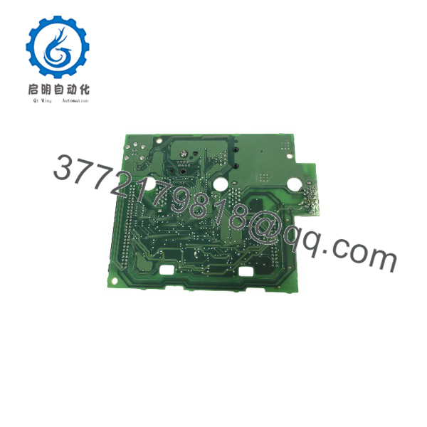
YPHT31600
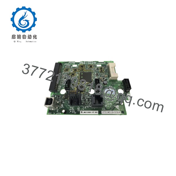
YPHT31600
Engineering Selection Highlights
- Centralized Motion Processing: Executes complex V/f, open-loop vector, or closed-loop vector motor control algorithms.
- Real-Time Fault Diagnostics: Performs continuous monitoring for short circuits, earth faults, phase loss, and overtemperature conditions.
- Optoisolated Signal Architecture: Features onboard optical isolation to guard sensitive microprocessors against high-voltage backplane transients.
- Plug-and-Play Drive Replacement: Standardized connector layout allows direct module replacement during drive maintenance and repair.
- Firmware & Parameter Backup: Integrates onboard non-volatile memory to retain motor configuration parameters during power-down cycles.
System Compatibility & Integration Requirements
| Item / Dependency | Verified Compatibility or Requirement | Practical Note |
| Target Drive Series | Yaskawa P1000 Series & Industrial Inverters/Servo Amplifiers | Verify exact sub-revision (e.g., -1D, -1E) against existing drive BOM. |
| Power Supply | Internal multi-rail DC supply from main drive power board | Receives operational voltage upon drive energization. |
| Firmware Revision | Drive-specific EEPROM firmware | Parameter transfer or EEPROM swap may be required when replacing the board. |
| ESD Handling | Anti-static precautions mandatory | Use ESD wrist straps during installation to avoid component damage. |
Dimensions, Mounting & Connection Notes
- Mounting Method: Secures onto internal chassis standoffs inside the inverter enclosure via mounting screws.
- Connector Interfaces: Multi-pin ribbon cable headers for power board interconnections, plug-in terminal block headers for external I/O, and dedicated keypad ports.
- Installation Precaution: Disconnect all AC line input power and wait at least 5 to 10 minutes for DC bus capacitors to fully discharge before opening the drive enclosure or replacing the PCB.
FAQ
What is the Yaskawa YPHT31600?
The Yaskawa YPHT31600 is a main control circuit board used inside Yaskawa AC drives, P1000 series inverters, and servo amplifier units.
What do the suffixes (like -1D or -1E) mean?
The suffix designations (e.g., YPHT31600-1D, YPHT31600-1E) indicate hardware revision levels, component updates, or factory firmware pre-loads.
Can I replace the YPHT31600 board without replacing the whole drive?
Yes, replacing the YPHT31600 control board allows you to repair a damaged drive control section without replacing the entire power chassis.
Do I need to reload parameters after replacing this board?
Yes, because motor parameters and application settings are stored on the control board’s memory, parameters should be backed up to the operator keypad or software tool prior to replacement and restored to the new board.
What protective functions does the board handle?
It processes thermal overload, overcurrent, overvoltage, undervoltage, ground fault, and communication loss protection logic.
Verification & Troubleshooting Notes
- Pre-Power Installation Check: Ensure all multi-pin ribbon cables and harness plugs are fully seated in their matching headers on the PCB before applying power.
- Parameter Reconciliation: If the drive displays parameter error faults (such as CPF errors) upon startup, re-initialize drive parameters to factory defaults and restore stored application settings.
- Visual Inspection: Inspect high-density surface-mount components and optocouplers for thermal discoloration or physical damage if troubleshooting drive trip conditions.